Showcase night part 1
Showcase night part 2
Final Milestone
This is my final milestone. In this milestone, I have completed building my chassis and finished programming in OpenCV libraries. That means, my base project is done, and now I have an object tracking robot that utilizes computer vision to recognize an object and automatically follows it.
Once I run the object tracking program, the robot keeps rotating right until it sees this red ball. When it sees the ball, if the ball is within the center range of the camera vision, it directly goes towards it and stops when the ball is 20 centimeters away. But if it the ball is outside that center range yet inside the camera vision, it automatically adjusts its initial position, then goes towards the ball and keeps rotating to ensure that the ball is always within that center of the camera. Finally, if the ball moves away from the camera vision, it rotates in the direction that it last saw the ball.
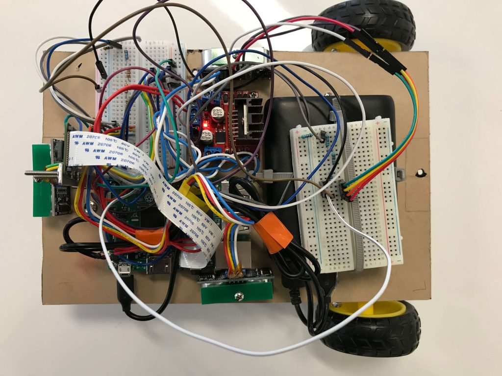
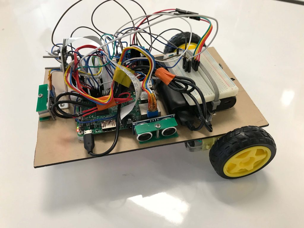
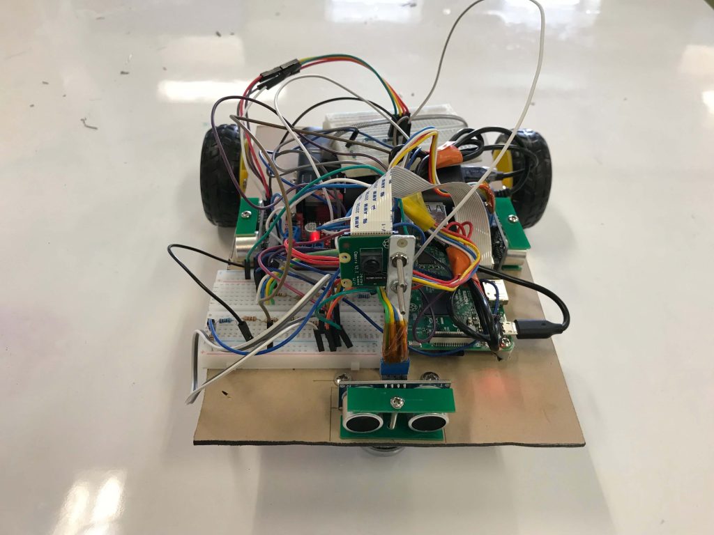
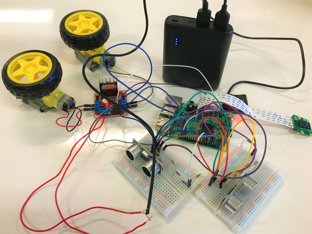
Before programming in openCV, the first thing I needed to do was to build the chassis. So I measured all the individual components and then created a design for my chassis. This is my design for the top part, which includes a power bank, the Raspberry Pi, the h-bridge motor driver, a breadboard, and two ultrasonic sensors, which I added in another one later on. For the bottom part, there is a caster wheel and two DC motors that are connected to the chassis with L-shaped brackets.
Then I worked with the openCV libraries for the object tracking part. The way that my robot worked is that it turns on the raspberry camera and sets the resolution to 120px * 160px and the framerate to 16. Then it analyzes each frame with the openCV library using two different color spaces in order to identify the largest red blob appearing in the camera to gives that blob an x-y coordinate set. From that my robot knows which direction the ball is, whether at the center, left of center, or right of center.
One of the most significant challenges I faced was that my robot would march forward even if it saw any objects in orange or even yellow. After researching and debugging, I realized that the HSV color space, which is a color system that focuses on separating the different variations of one particular color, is ineffective when external light comes into play. The way I resolved this was by adding in the YCbCr color spaces that is robust towards external lighting changes. And then I converted the image into grayscale with erosion and dilation to avoid the unnecessary details in camera.
Another challenge I faced was that my robot would not go into a straight line because the two motors did not spin at the same rate, meaning that the right motor spins a faster than the left motor. So I adjusted the PWM, which stands for Pulse Width Modulation, to control the amount of voltage being sent to the motors. So if I change the PWM output of the right motor to 80%, the right motor will spin at 80% of its original spin rate.
Before coming to BlueStamp, I have only worked on programming in Snap and Python, and I had only little experiences with electronics. But throughout the program, I have learned fundamental soldering, drilling and sawing skills when creating my robot. Besides that, I have also developed an interest and passion in both electrical and software engineering. In the future, I will add in more features for my object tracking robot, such as machine learning to make it more reliable. And I will also participate in more engineering programs to work in more intensive projects that require a combination of both hardware and software.
Second Milestone
This is my second milestone. By now, I have setup the VNC, which stands for Virtual Network Computing, between my laptop and my Raspberry Pi, that means I can directly access the raspberry pi desktop from my laptop without physically using a monitor. To do this, I first needed to install the VNC server on the raspberry pi. But since the raspberry pi already has the VNC server pre-installed, what I did was to enable the VNC module on my Raspberry Pi through its configuration and restarted it in order for the module to take effect. After that, I downloaded the VNC viewer on my laptop and connected to the raspberry pi by adding its private static IP address. The reason why I did this was because the static IP connection that I used before with the ethernet cable does not provide internet access to my Raspberry Pi. The ability to remote control offers me a lot more flexibility and allows the robot to not be restricted by the length of the ethernet cable.
In addition to the VNC, I was also able to connect the camera to the Raspberry Pi and use it to take still pictures and do live stream. To take a picture, I wrote a python program to first let the camera start previewing for 5 seconds, which allows to me adjust the position of the camera, then capture a still picture at the fifth second and stop previewing after all. To do a live stream is a lot more complicated. First, I needed to import all the necessary libraries. Then, I created a temporary html website that only exists when the camera is live streaming. After that, basically what the camera does is rapidly capture a sequence of images with lossy compression, saving them to the disk, and uploading them to the temporary streaming website. It’s obvious that lossy compression has decreased the quality of the individual images and therefore the overall quality of the streaming video. But that allows the images to be uploaded much more quickly.
My robot also uses ultrasonic sensors. Those sensors are used to measure the distance to objects using sound waves. There are four pins on the sensor, the vcc pin, the trigger pin , the echo pin, and the ground pin. First I connected the vcc pin to the 5 voltage output on the Raspberry Pi, and the ground pin to the ground pin on Raspberry Pi. The way it works is that the trigger pin 8 cycle sonic burst that travels at the speed of sound, and then the echo pin will output the amount of time in microseconds the sound wave travelled. After that, I used the equation speed equals two times the distance divided by time, because the sound wave travels to the object and bounces back. Since sound wave travels at 340m/s, I substituted the value in the equation and simplified it. So I got the final equation distance equals 170m/s times the amount of time in microseconds.
The other part of the computer vision that my robot uses is the ultrasonic sensors. Those sensors are used to measure the distance to objects using sound waves. There are four pins on the sensor, the vcc pin, the trigger pin , the echo pin, and the ground pin. First we connect the vcc pin to the 5 voltage output on the Raspberry Pi, and the ground pin to the ground pin on Raspberry Pi. The way it works is that the trigger pin initiates 8-cycle sonic burst that travels at the speed of sound, and then the echo pin will output the amount of time in microseconds it took the sound wave travel back to sensor. After that, we use the equation speed equals two times the distance, because the sound wave travels to the object and bounces back, divided by time. Since sound wave travels at 340m/s, we substitute the value in the equation and simplify it. So we get distance equals 170m/s times the amount of time in microseconds.
My next goal is to set the openCV to allow the computer to recognize objects appeared in the camera. Then the final step will be incorporating all my previous codes into one program, building the chassis and assembling electronics.
First Milestone
Starter Project
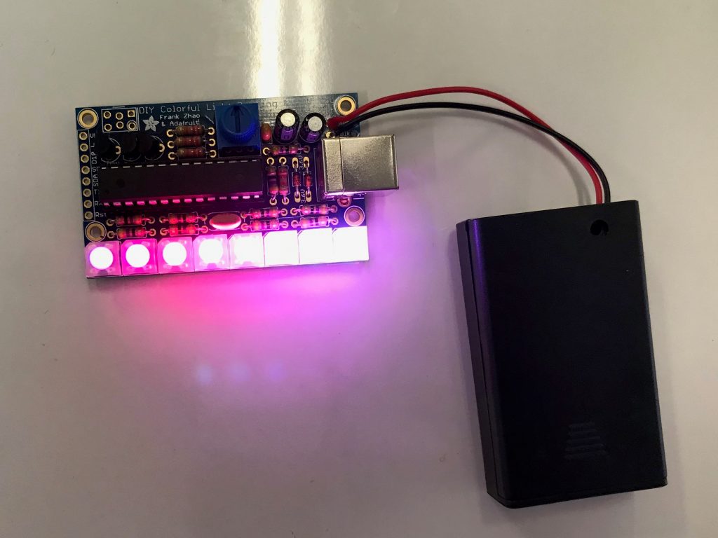
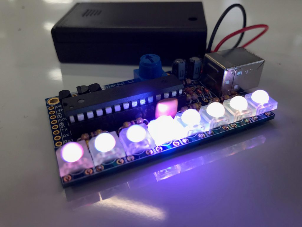
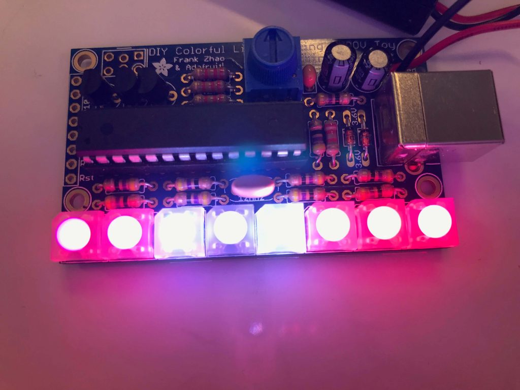
For my starter project, I assembled the Mini Pov, which allows me to display a particular image as it moves using eight LED lights. In order to do this, each LED light flashes at a specific frequency and with various colors. By connecting the device to my laptop, I am able to alter what the Mini Pov displays by downloading the Mini Pov 4 programming software and utilizing the image converter. The purpose of this is to display a particular image when I wave it back and forth in the air.
The Mini Pov 4 is powered by three 1.5 volts AAA batteries. By turning on the switch on the battery holder, the current first goes through the two six volts capacitors, which store the potential electrical energy in an electric field and ensure that exactly six volts are produced as an output. Then, the current passses through three 2.2k ohms resistors that restrict and balance out the amount of current going into the transistors. When the current reaches the three transistors, the transistors apply voltage between the emitter and the collector to turn on the transistors so that current will be allowed to flow from the base to the emitter. They primarily act like amplifiers and control the red, green, and blue colors of the LEDs.Next the microcontroller, the most crucial component, stores the image and keeps track of the flashing of the LED lights. And finally the eight 47 ohms resistors ensures no excessive current is being sent to the LED lights to prevent malfunctioning and overheating. We also have a potentiometer to set the speed of the LEDs. The ceramic capacitor stabilize the output voltage and keeps the current at a constant value. And finally, the crystal oscillator acts like a clock and function with the microcontroller.
The most significant skills I learned was soldering and desoldering. Those skills are fundamental to electrical engineering and I have gained valuable experience. Besides that, I became more proficient at debugging by using a multimeter to examine the different components in the circuit when one of the LED lights didn’t flash because of incomplete soldering.