Building an Amazon Echo

Hello, my name is Eric and I am a rising senior at KIPP King Collegiate High School. My main project is to create an Amazon Echo using a Raspberry Pi 3.

Engineer

Eric L.

Area of Interest

Computer Engineering

School

KIPP King Collegiate High School

Grade

Incoming Senior

Modifications

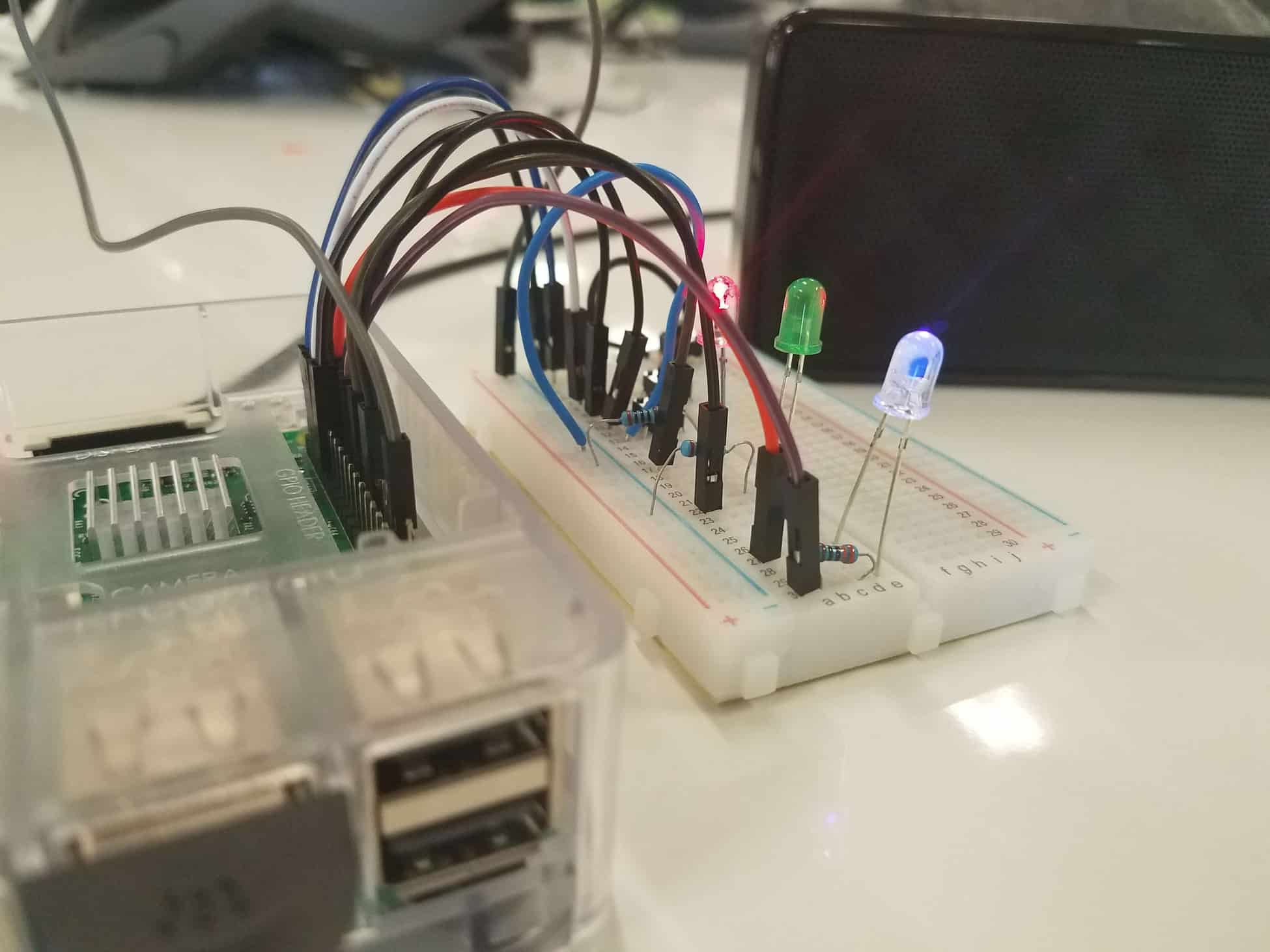
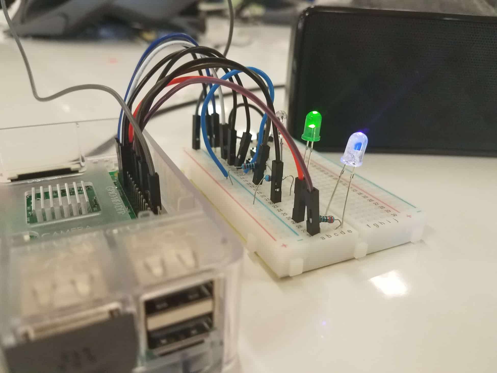
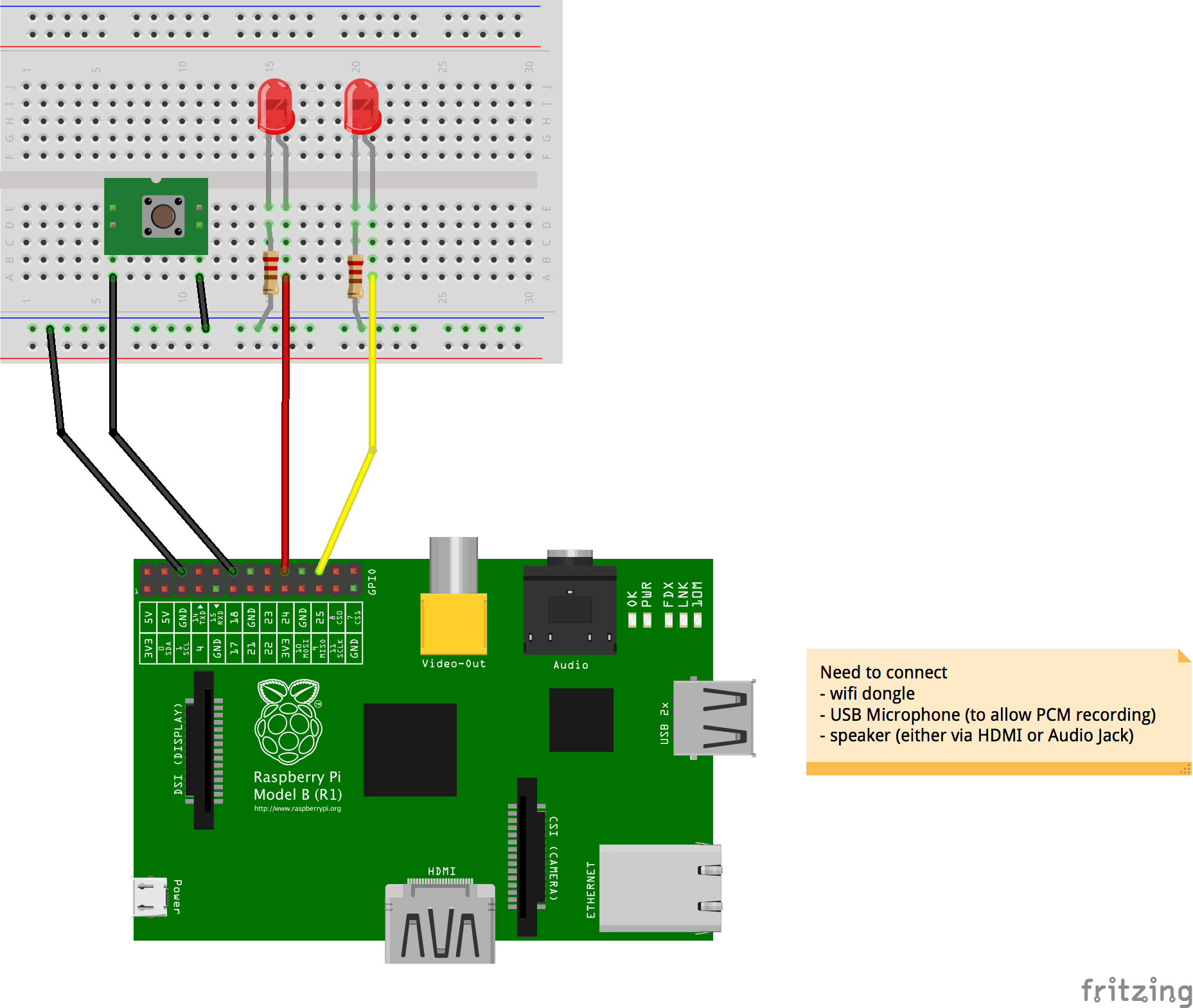
After finishing my final milestone for my base project, I added modifications to my Amazon Alexa. In order to closer resemble a consumer Amazon Alexa, I added a power button and mute button to my AlexaPi. The power button would run the “sudo shutdown -h now” terminal command to shutdown the Raspberry Pi when pressed. There is also a blue LED indicator for when the Raspberry Pi is on or off. When the LED is off, it is safe to unplug the Raspberry Pi. Afterwards I created a mute button that would toggle the USB microphone of the Raspberry Pi on or off. In order to indicate when the AlexaPi was listening to the user or playing back/speaking, I used a red LED and green LED. The green LED would light up when the AlexaPi was recording the user’s voice, while the red LED would light up when the AlexaPi was speaking back to the user. While adding these modifications to my AlexaPi, I had difficulty understanding how to create LEDs that would correspond with Alexa recording or playing back. At first I attempted to modify the mute button program to include the LED lights. However, this was difficult to do given my unfamiliarity with programming as a whole. So, I attempted to find a solution using a circuit and found that the base installation of AlexaPi already included these features. In order to utilize these features, I had to create the circuit shown in the AlexaPi schematic on my own breadboard. Since some of the GPIO pins in the schematic were already being used by my power button program, I had to research online what other GPIO pins on the Raspberry Pi had the same function and use those instead. Once I completed both the LED circuits, power button, and mute button, I was finished with my modifications to make my AlexaPi more closely resemble an Amazon Alexa.

Final Milestone

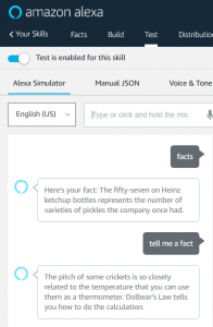
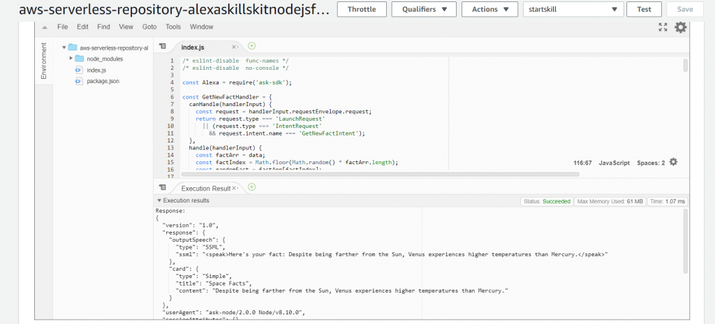
For my final milestone, I wanted to display the abilities of my Amazon Alexa on the Raspberry Pi. Like your consumer Amazon Alexa, the AlexaPi is able to use custom skills you make. Using an Amazon Developer and Amazon Web Services account, I was able to create a skill called Facts. In the developer portal, I first had to create an invocation name “Facts” in order for Alexa to recognize the skill and understand what program to open when I wanted to use the Facts skill. Next, I had to go to the intents tab and write sample utterances a user may say in order to invoke the program. For example, a user may want to say “give me a fact” rather than “tell me a fact” to invoke the “Facts” skill. For the base coding of the skill, I incorporated the “skill-sample-nodejs-fact” source code provided by Amazon into the JSON code editor of the skill. Using my Amazon Web Services account, I modified the selection of replies and facts the Facts skill could choose from. To do this, I created a function for the skill through Amazon Web Service’s Lambda functions. In the function, I inputted new facts my “Facts” skill would be able to choose from into the “index.js” file of the function. The function had an Amazon Lambda ARN or Amazon Record Number, which I inputted into my “Facts” skill as an endpoint. This made the skill use the function I made that had all the facts I wanted Alexa to choose from. After creating the functions and skill, I used the built in testing mode of the Amazon Developer portal to make sure the skill worked as intended. During this process, I had difficulty with programming the function to use the facts I inputted into the program. On my first attempt, I modified the data of the function incorrectly by creating a second “index.js” file in the function to add new facts rather than editing the “index.js” file already provided by Amazon Web Services Lambda. To fix this issue, I deleted the function and skill since the endpoint had a failed execution of the function. After deleting the function and skill, I restarted the process from the first step with Amazon Developer’s skills kit and was able to finish creating my Facts skill. 

First Milestone

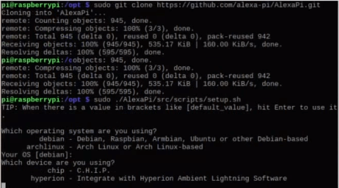
For my first milestone, I installed the base program for the Amazon Alexa on my Raspberry Pi. In order to do this, I first installed Raspbian onto the SD card of the Pi. After that, I had to create an Amazon Developer account and create a profile for the AlexaPi. Next, I installed git onto the Pi. Using git, I cloned the AlexaPi from github. Once the AlexaPi scripts were done being copied over, I answered the setup questions it asked. Finally, I rebooted the machine and started the AlexaPi using the terminal command “sudo systemctl start AlexaPi.service”. During this process, I had difficulties with getting the microphone to be detected by the Raspberry Pi. In an attempt to solve this and other audio issues I came upon, I formatted the SD card and redid the steps from the beginning. An issue I continue to have is setting up SSH with the application, Putty, to connect my laptop to the Raspberry Pi terminal. For the first day I setup SSH, I used an Ethernet LAN network adapter and this was successful. However, after that day, SSH would not work and could possibly be a result of the Ethernet network adapter not working. To be more efficient with my time, I used an external monitor with keyboard and mouse instead of SSH.

Sources

https://github.com/alexa-pi/AlexaPi

https://github.com/alexa-pi/AlexaPi/blob/master/Circuit%20diagram_bb.png

Starter Project

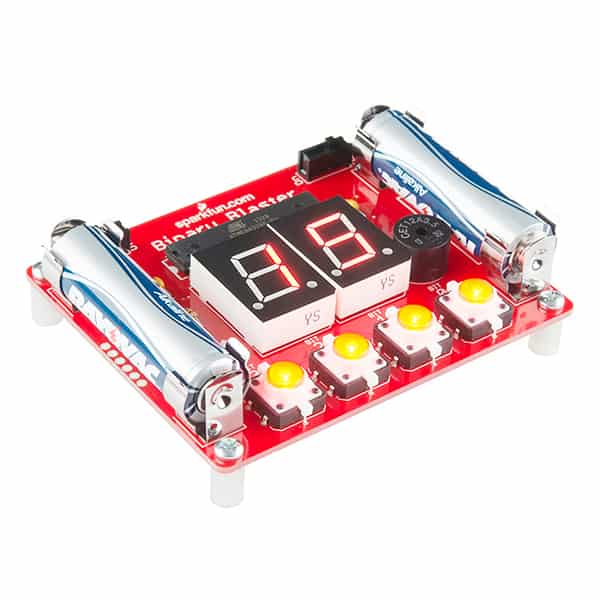
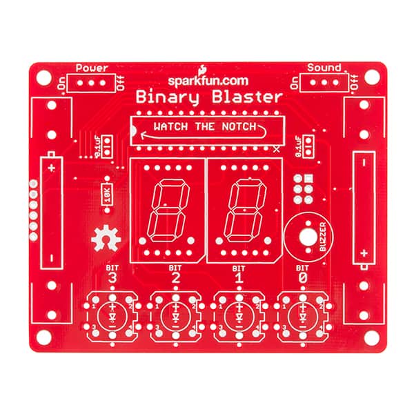
My starter project was a Binary Blaster. The Binary Blaster is a game that asks you for the binary equivalent to a number and the player has to respond by pressing the LED button where the 1 should be in its binary equivalent. At the end, a score displaying how much time was spent to complete all 15 numbers. For this project, there are two switches. There is a switch for the power and sound. By turning the switch from off to on, it completes the circuit for its respective part. An ATmega328 is used as the microcontroller. The ATmega328 contains the code for the game. There are two batteries on the board, and these batteries allow for the flow of electrons in the circuit. Next, there is a brown, black, orange, and gold striped resistor. The first two bands of the stripes being brown and black displays the resistor’s value of 10 Ohms. The third band being orange represents its weight value, while the gold final band displays the resistor’s tolerance of ±5%. This resistor controls the flow of current in order to not overflow the other components with current. There are two ceramic capacitors on the board. In these capacitors, the battery induces electric potential across the capacitors where electricity will be stored. When the capacitor is full of electricity, it discharges the extra electricity to the LED buttons and display. The buttons and display use LED or light emitting diode. The LED converts the electric current sent to it in order to display light.  There is also a 12mm speaker that uses an alternating current in order to drive a thin metal sheet to vibrate with an electromagnet. This speaker only works when the circuit to it is completed by turning on the sound switch. Lastly, the Binary Blaster uses a 7-segment LED display in order to show the number provided by the microcontroller.

Sources

https://learn.sparkfun.com/tutorials/binary-blaster-assembly-guide?_ga=2.212103959.207714790.1531255296-831155585.1529356361

Leave a Comment

Start typing and press Enter to search

Bluestamp Engineering