Fingerprint ID Safe with Keypad
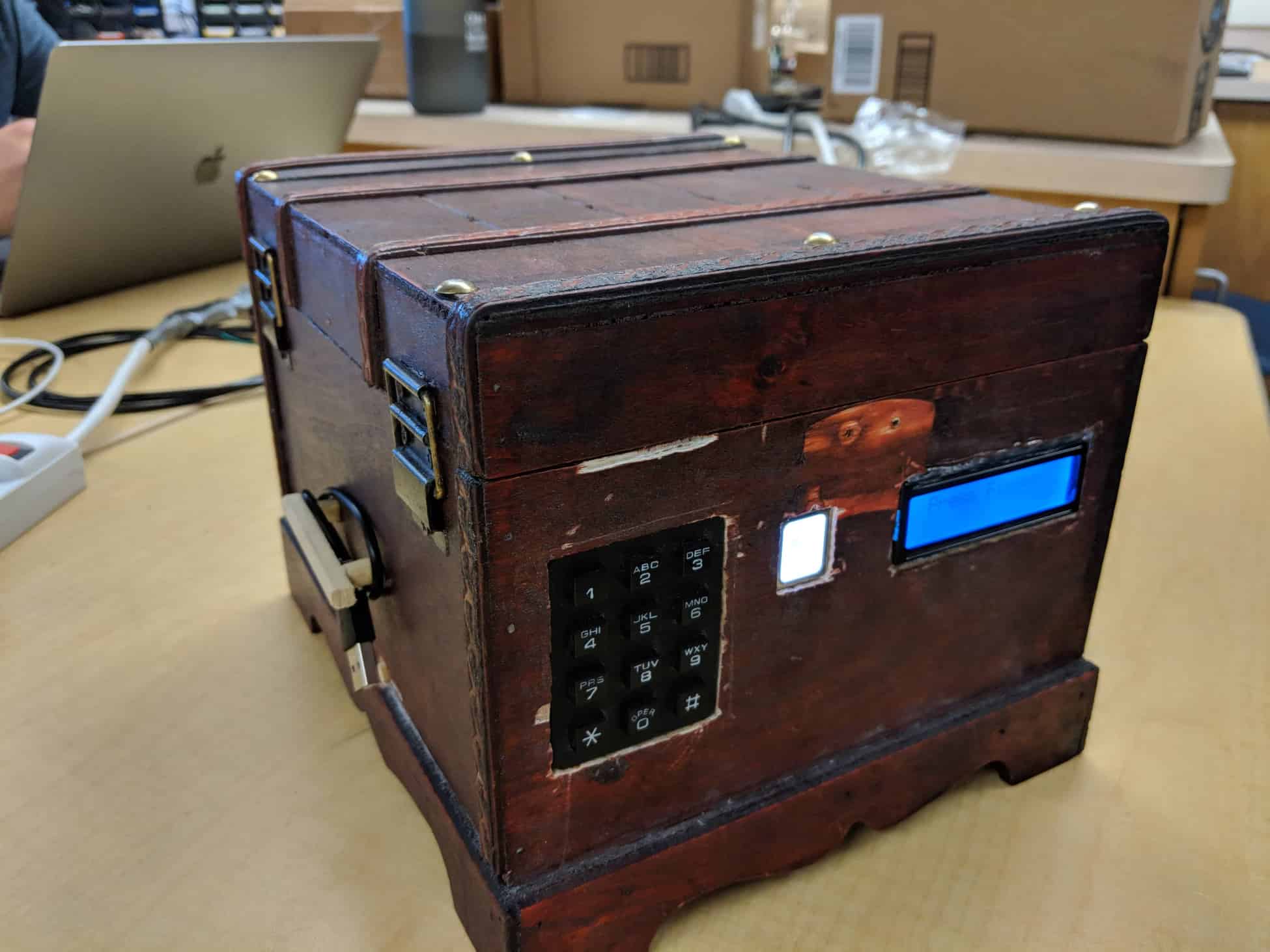
The Fingerprint ID Safe is a safe the needs a combination code and the owner’s fingerprint to unlock it. To access the safe, you must first enter a password, and if you get that correct, then you have to press your finger to the fingerprint sensor. If your fingerprint is recognized, then the safe unlocks. For a locking system, I used two L connectors and a servo. This project is a challenge in both hardware and software aspects, but is a very rewarding build once completed and a nice way to store your possessions.
Engineer
Luca C
Area of Interest
Hardware Engineering
School
Los Altos High School
Grade
Rising Sophomore
Reflection
Overall, Bluestamp has been a great experience and I have learned a lot about different kinds of engineering. This was my first time doing a program that was so engineering intensive and I had not been exposed to much engineering in the past. All I knew was that I had a small interest in building and design and this camp sounded like a good opportunity to explore that. This camp was so much more different that I expected from the very beginning. On the first day, I was already building my starter project within half an hour of walking into camp. Bluestamp was focused on independence and I was mostly researching solutions to my project instead of having lectures. This camp has also piqued my interest in hardware engineering and has opened up a potential career path for me.
Demo Night
Final Milestone
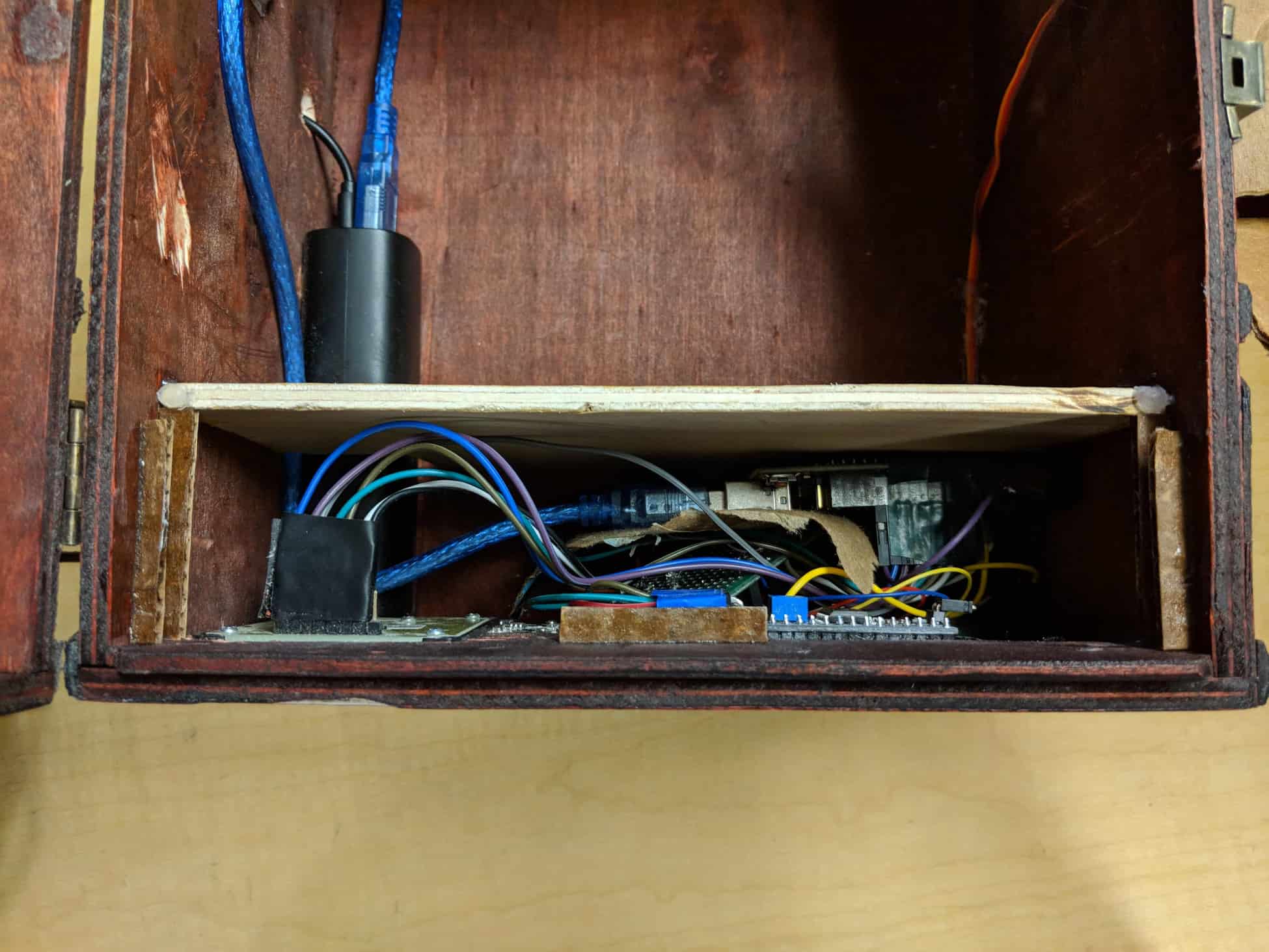
For my final milestone, I put the finishing touches on my safe. I cut out spaces in my box to fit my fingerprint scanner and keypad along with a small hole for a charging cable. I also glued in my servo to created a lock mechanism and added a Liquid Crystal Display to display text. Another feature that I incorporated was a buzzer to make a “beep” sound as I punched in numbers and once I successfully unlocked my safe. Furthermore, I finalized my code and made sure all my connections were secure to prevent connectivity problems. A few issues I had to overcome were some of the connections on my PCB which were not soldered correctly and had messed up my circuit. I used a multimeter to check the voltage running through different places to find out where the problem was. Once I found it, I just soldered the wires back together. Additionally, using a Dremel to cut out spaces in my box was long and tedious work and I ended up doing a shaky job. However, I was able to file out most of the rough edges and have my components fit tightly. Unfortunately, I cut too much for my LCD and there was extra space on the top and bottom. Since it fit well horizontally, I was still able to make it fit into my safe. To make sure my components stayed in my box, I superglued them in.
Second Milestone
For my second milestone, I incorporated my fingerprint scanner into my project. I had a system where when I entered the correct password on my keypad, my fingerprint scanner would light up and I could scan my finger. If my fingerprint was recognized, then my servo would turn and I could press the hash key to return my servo to its lock stage. This milestone was more difficult than my first because my fingerprint scanner was more difficult to connect and program. At the beginning, I had trouble getting my fingerprint scanner connected to my Arduino because my connector had ends that would fit my scanner, but not on a breadboard. At first, I cut off the ends and soldered on ends of male wires so I could connect them to a breadboard. That ended up not working because the wires would fall off, so I had to get connecters that had male heads already built into one end. I also had an issue with getting the correct amount of power to my scanner. I did not know how to create a voltage divider at the time and I spend hours trying to figure out how to get power to my sensor and how a voltage divider worked. After I got that to work, things got easier. I loaded some sample code onto my Arduino to enroll my fingerprint and then added some code to my main program. Unfortunately, my servo would twitch in between the time where I enter my passcode and press my finger to the sensor and I plan to fix that in my final milestone. Additionally I will also be transferring my wiring to a PCB and putting everything into my box.
First Milestone
My first milestone was getting my servo to respond to a certain passcode that is typed into a keypad and ignore incorrect ones. I experienced problems from the start such as not knowing how to connect each of the pins on my keypad to the Arduino. I troubleshooted by downloading some code and testing each pin on the keypad. Once I found the first two pins, it got easier to find the rest and I was eventually able to get all my pins hooked up so that when I pressed a key, the corresponding number would appear on the serial monitor. Next, I had to figure out how to code a password system and connect a servo to my Arduino. It took a while but I was able to work out a system using two variables. I had an integer variable with my set passcode and another variable with the inputs from my keypad merged into a single number. Then, the inputed password is compared to the set one and if the numbers match up, then the servo turns and if they don’t, the the servo does not turn. For my next milestone, I plan to incorporate my fingerprint scanner to make a two step process for moving a servo.
Starter Project
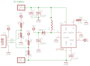
My starter project was the Minty Boost, a battery powered charger. It uses multiple components to create a suitable voltage to charge a device. It uses a 3.3k resistor to improve current capability. There are four capacitors, one filters out high frequency noise to make a smooth output and another keeps the chip stable to create a precise voltage. The other two are electrolytic capacitors and stabilize both input and output voltages. A diode makes sure power is only transferred from the battery and not back to it. The Minty Boost also uses an inductor to stabilize current. The Minty Boost takes a total of three volts from the two AA batteries and runs it through a circuit. The resistors and inductor stabilize the voltage and transfers it to an IC chip, which amplifies it to five volts, which is ideal for charging a device.


