Reflection
The six weeks at BlueStamp were very memorable. I came to BlueStamp for a hands-on engineering experience. It was rewarding to get to apply the knowledge I learned in school to an actual project, an RC robot tank. I had never used Arduino before I came to BlueStamp, so coding in Arduino was hard for me in the beginning. But, it eventually became easy when I familiarize myself with it. I really appreciate the ideas that Bluestamp reinforced on us, i.e, we should try our best to think of possible solutions before we ask for help. Most of the time, after trying my best to solve a problem, I would be able to either solve the problem already or at least have a better understanding of how I should approach the problem. I truly enjoyed my time at BlueStamp.
Second Modification
Second Modification
I first worked on coding the Arduino for the automated guiding mode. Using the ultrasonic sensor to calculate the distance, I programmed the Arduino so that if an object is within 15 centimeters on the left side of the tank, the tank would go forward. If the tank encounters an object within 15 centimeters in front, it would try to make a left turn. If there are objects on both the left side and in front of the tank, the tank would make a right turn.
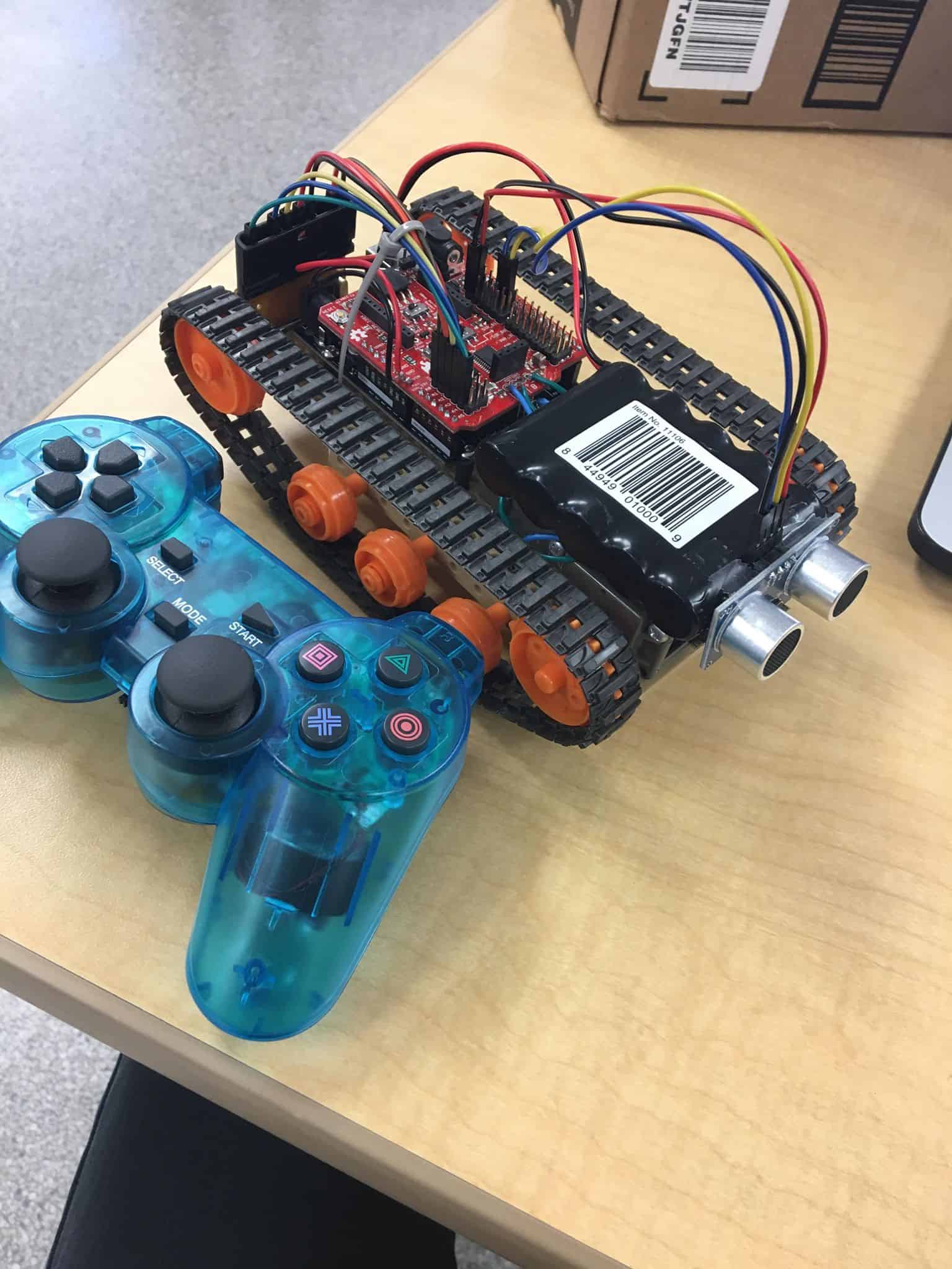
After running a test of the tank guiding itself. I tried to combine that code with my original remote control code. At first, I could not successfully switch between two modes. I solved the problem by putting the automated guiding code under the condition that the controller is not found, so whenever the controller is found, the Arduino would not enter into automated guiding part of the loop. So now, I can both have the robot tank to guide itself automatedly and control it with the PS2 controller.
Here is the code I used for RC and Automated Guiding.
First Modification
First Modification
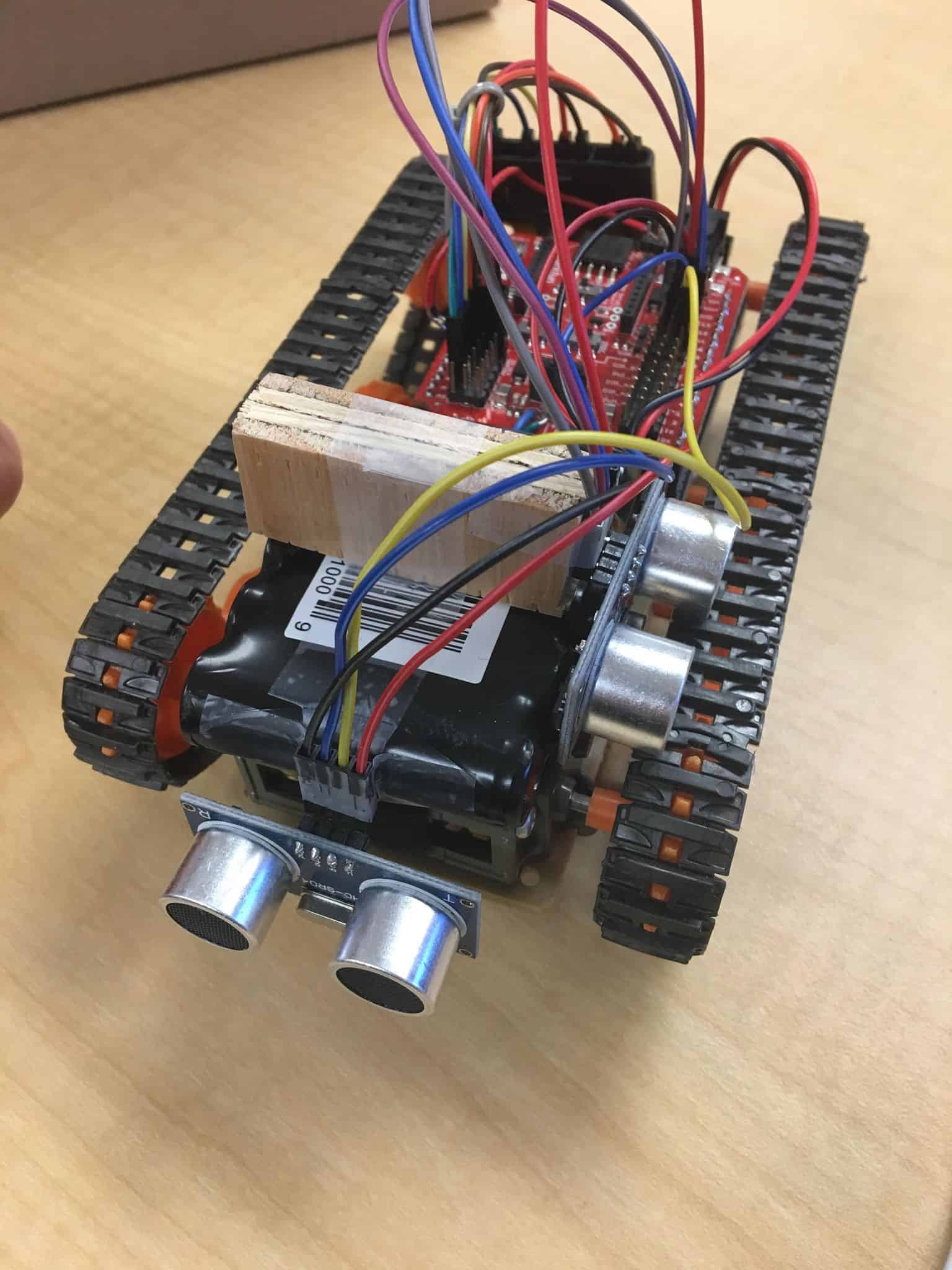
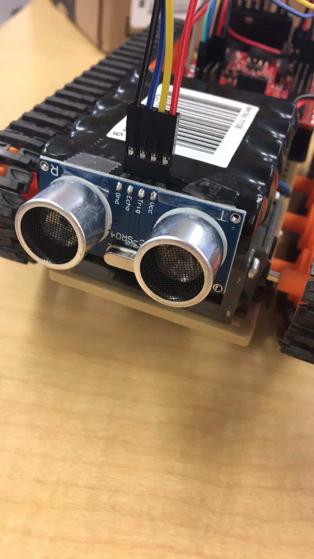
First, I connected power, ground, trigger, and echo pins of the ultrasonic sensor to the motor shield using jumper wires. Then, I worked on the code that will let the ultrasonic sensor calculate the distance between the tank and the object the tank is approaching. The ultrasonic sensor functions in the way that the trigger sends out an ultrasound as an output and the echo receives the ultrasound as an input after it reflects back from the object. The sensor will measure the time it takes for the ultrasounds to return and use the speed of ultrasound to calculate the distance. I first started off coding the Arduino for the following: when the distance is within 6 centimeters, the motor would shut off. The problem was that as long as the PS2 controller is still sending instructions for moving forward, the motor will start moving forward again after it shuts off. Thus, I coded the Arduino in a way that once the distance between the tank and the object is within 6, the motors will run backward to back the tank up. And even if the PS2 controller is still sending forward instructions, the instructions will be canceled by the backward instructions and thus prevent the tank from running into the wall.
Here is the code I used to incorporate Ultrasonic sensor.
Final Milestone
Final Milestone
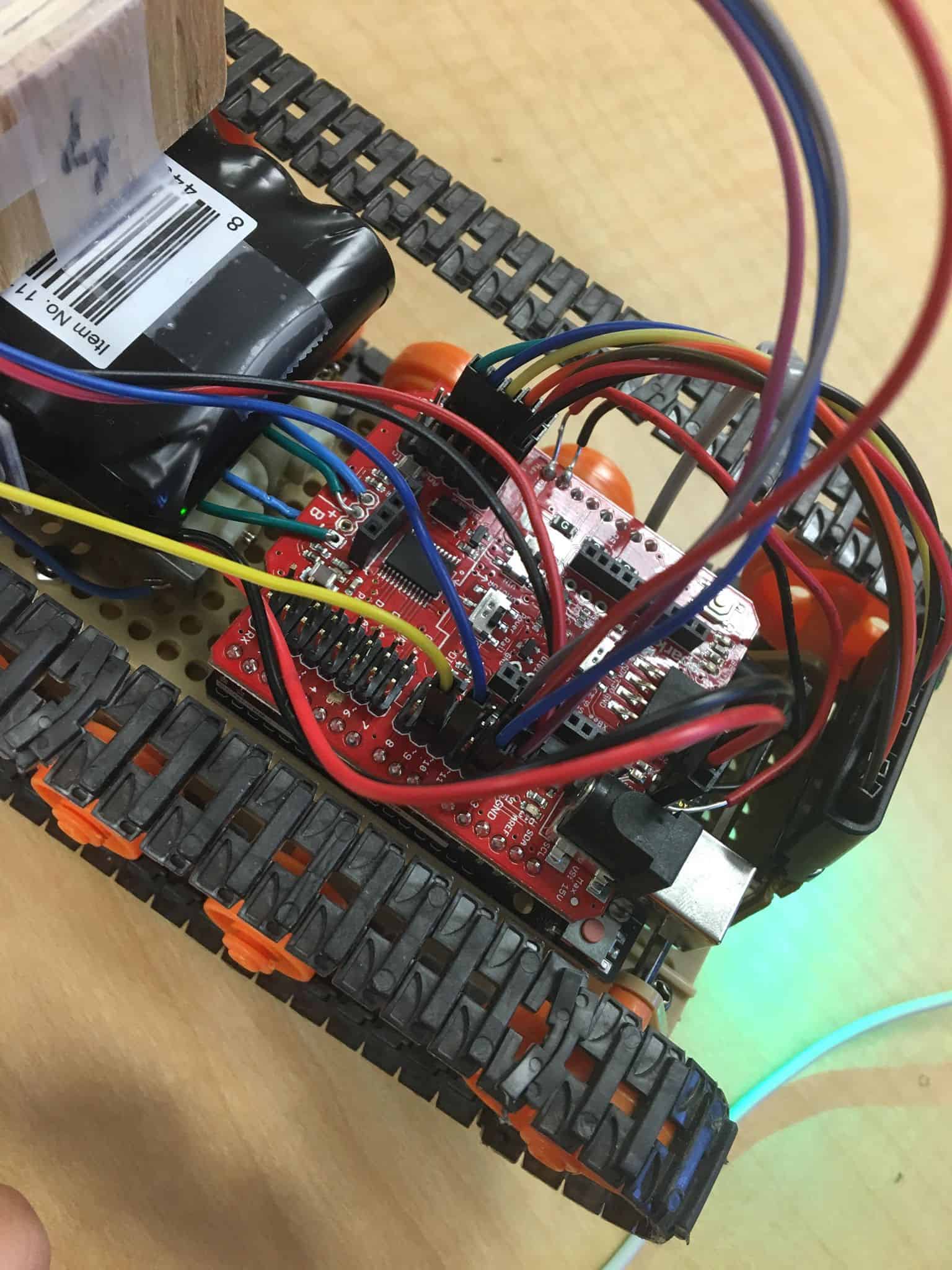
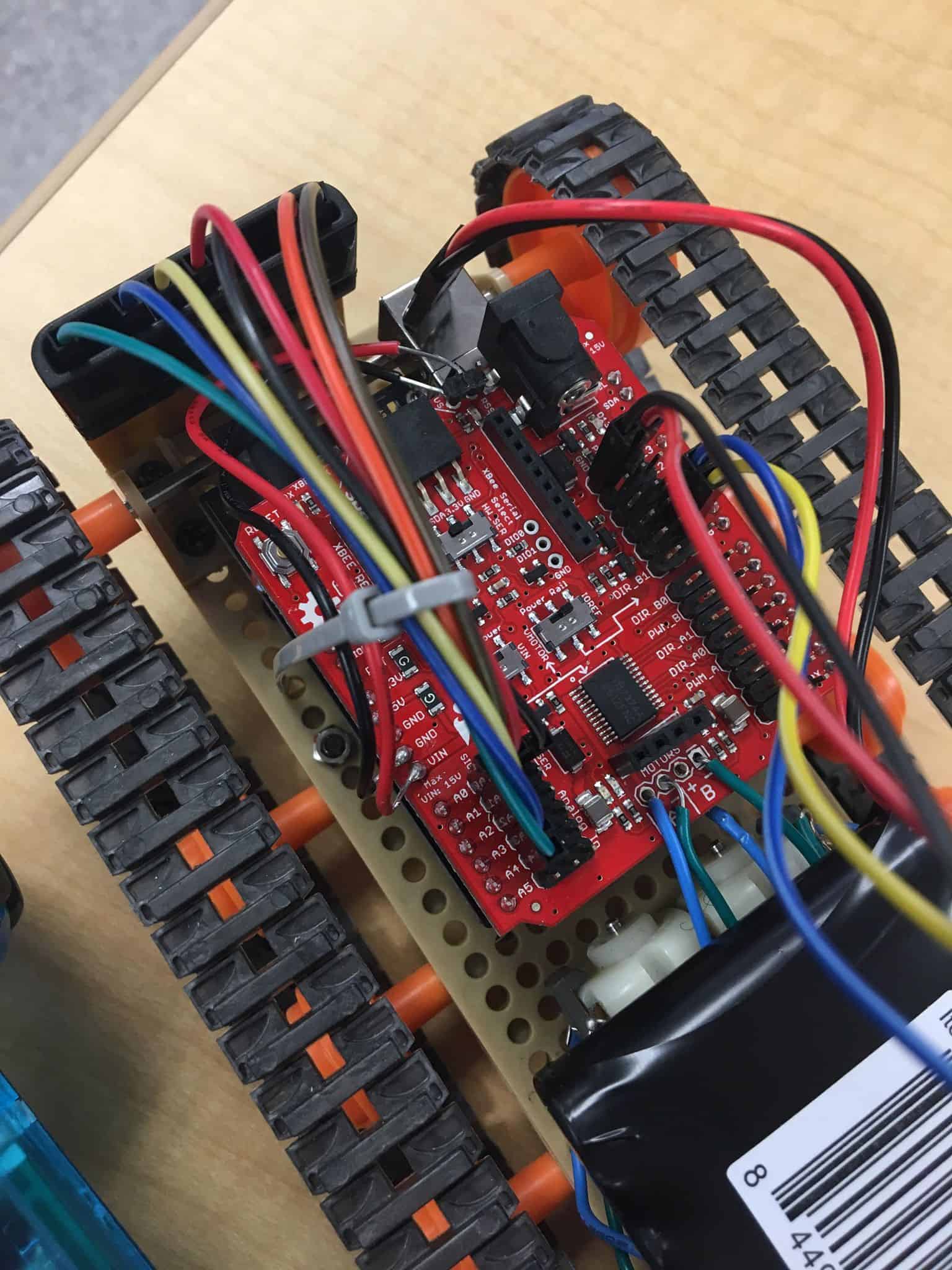
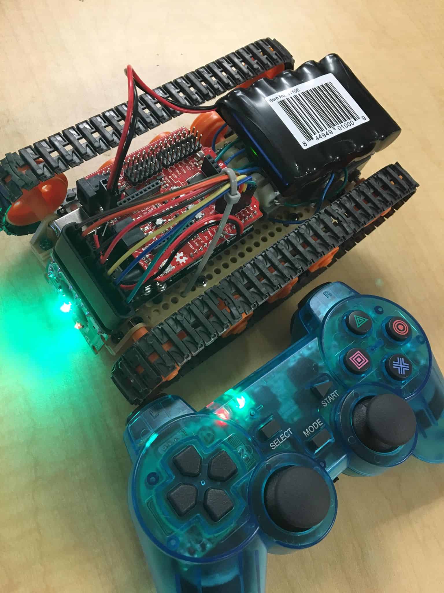
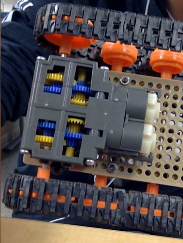
I started off by tearing apart the wireless dongle for the PS2 controller and then I connected the dongle to my motor shield by using multiple jumper wires. Then I needed to write a code for the motor shield to receive signals when different buttons on the controller are pressed using the PS2X Library. But when I tried to control the motors using the PS2 controller, I encountered a difficulty. Although the serial monitor was showing that the motor shield is receiving all the signals from PS2 controller very well, the motors do not respond to those signals at all. Through deeper research, I found out the problem was that my motors are not included in the Adafruit system. After studying my motor shield, I figured out that I need to use the servo library to control the motors. With a correct code, I was finally able to control my tank’s motion wirelessly using the PS2 controller. For example, when I press R2, the right motor will start rotating in the direction that brings the right side of the chassis into forward motion.
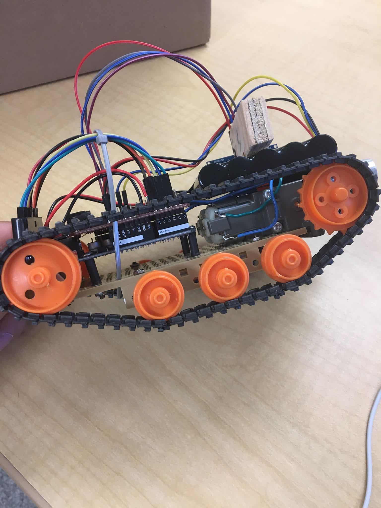
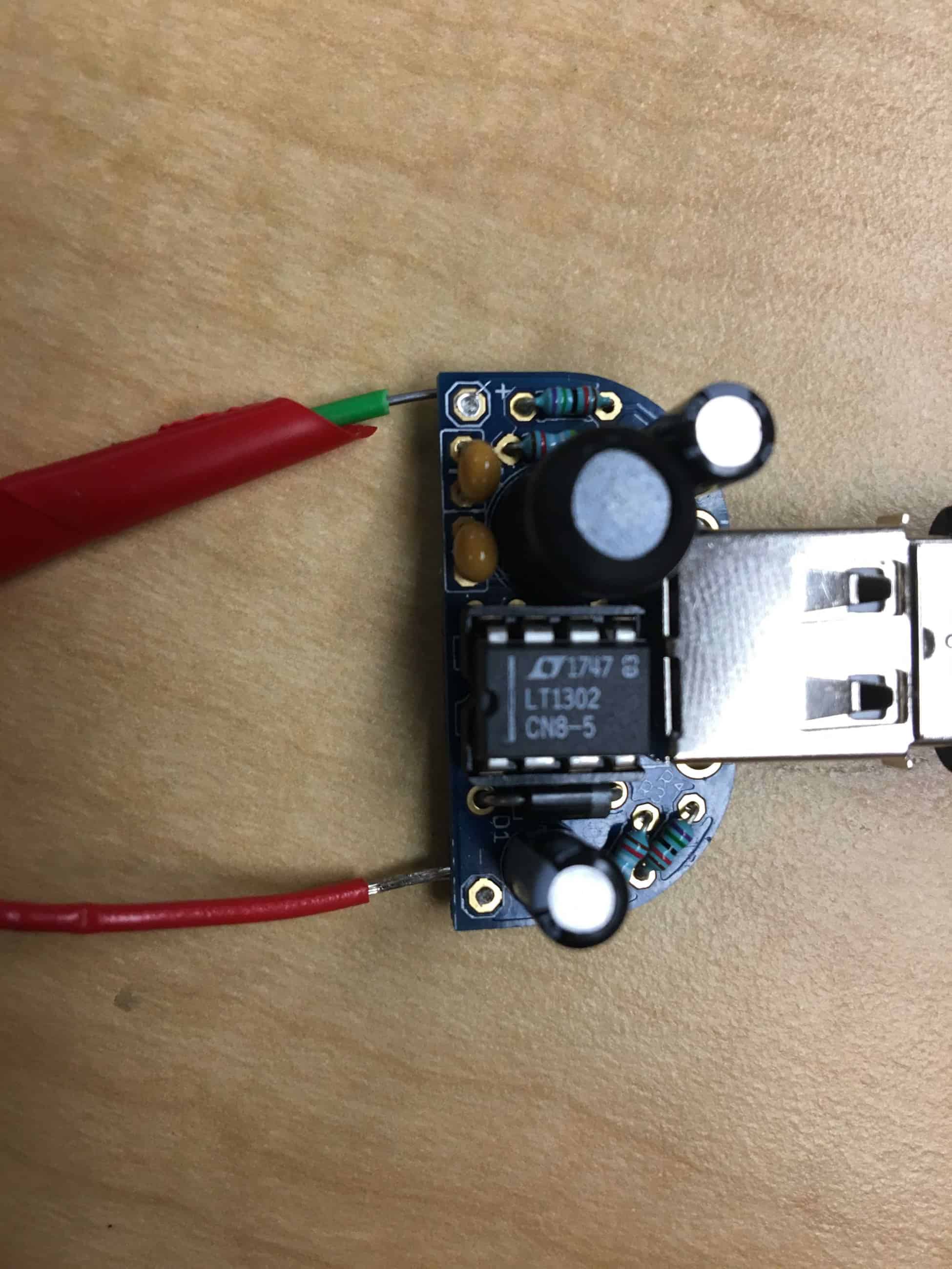
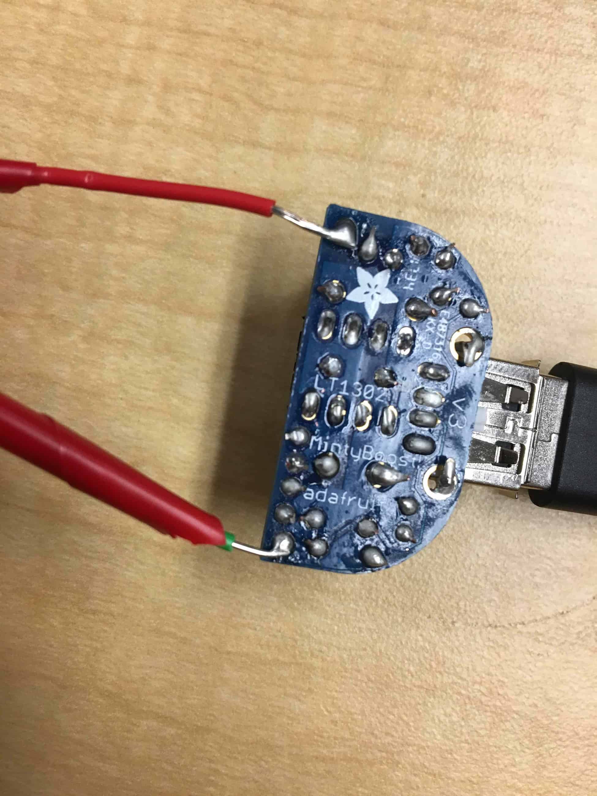
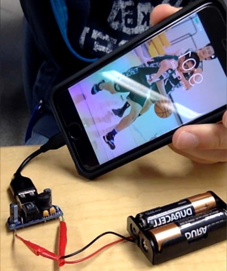
In the end, I worked on using just one battery source to power the Arduino board and the motors at the same time. I used to use two battery, one powering the motors through the power jack and one from the USB output powering the Arduino board. I soldered the ground and Vin pins that power the Arduino board to the ground and power pins of the voltage source that power the motors. Now I only need to power the voltage source and the Arduino board will also be powered. My next step would be to think of a few modifications, maybe adding an ultrasonic sensor or infrared sensor.
Here is the code I used for Remote Control.


