Theo C.

Hi, I’m Theo and I am a rising sophomore at Dwight-Englewood School For my starter project I built the electronic d6 for my dungeons and dragons games. For my main/intensive project, I decided to build a pair of RC tanks that can play laser tag with each other. I chose this project because it promises to be an interesting build, but mostly because who doesn’t want to play with RC laser tanks? Just the words ‘RC laser tanks’ are cool enough to justify the project.

Throughout this program, I have learned how to program an Arduino, improved my soldering skills, and became much more confident in my ability to build complex projects by breaking down the big problems into individual goals and tasks. I also learned to work, troubleshoot, and solve problems independently.

Engineer

Theo C.

Area of Interest

Aeronautical Engineering

School

Dwight-Englewood School

Grade

Incoming Sophomore

Final Project

My main project is a pair of Remote Control tanks capable of playing laser tag. Much of the basic assembly was straightforward, using chassis, track, and  gearbox kits.  The turret assembly was also relatively simple, but held up by delays of the photocell shipment. After realizing that the PS2 controller did not connect to its receiver reliably enough, I decided to switch to a home-made controller using NRF transceiver modules. The controller was much more difficult to build, as the cables that I used initially did not provide a solid connection. To solve this problem, I needed to replace the stranded wires with solid-core wires, and the header pins with solder joints. I also discovered that the Arduino library used to communicate with the NRF transceiver modules required pins that were also needed by the motor shield. In order to solve this problem, I had to swap pins 11, 12, and 13 with 2, 4, and 6 in order to both drive my motors and connect to the NRF. Since my last milestone, I completed the second controller to control my other tank. Throughout this project, I have learned how to program an Arduino, improved my soldering skills, and became much more confident in my ability to build complex projects.

DOCUMENTATION:

GitHub Repository (Code, Circuit diagram file): https://github.com/theoHC/Laser-Tank

Circuit Diagram:
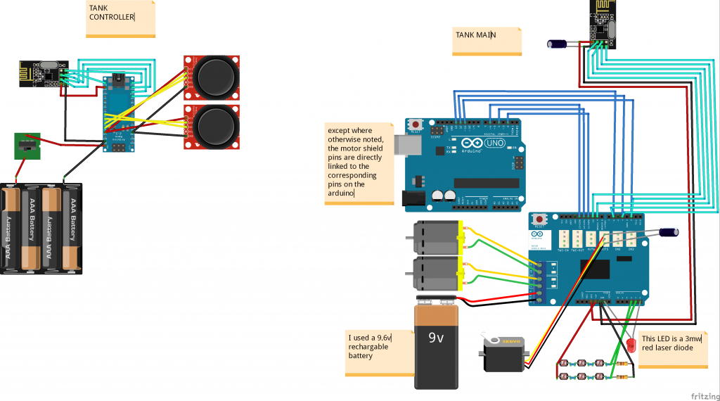
ltcircuitdiagram

Third Milestone

For my third milestone, I completed the radio control component of my tank, allowing it to maneuver and operate the turret using a  NRF transceiver and joystick based control assembly. During this phase of my project I had a huge amount of difficulty getting the transmitter and receiver components to communicate, with problems in the program, wiring, and connections. Fortunately, I rapidly got to the stage where everything that could possibly fail already had, so it worked. My next step is duplicating the RC and turret for my other tank.

Second Milestone

For my second milestone, I completed a device and program to detect a laser hit. I also built a controller using an Arduino Nano and a NRF transceiver module.  The biggest challenge I faced was needing to replace the PS2 controller with the homemade NRF setup because I could not get the PS2 controller and receiver to connect reliably. Another challenge I faced while working on this was needing to swap pins on the Arduino motor shield to accommodate the NRF.

First Milestone

For my first milestone, I completely assembled both tank chasses and drive trains and connected the PS2 controller to my Arduino so that a LED would light up when I pressed the triangle button. Two of the things that I struggled with were a backwards LED during testing and controller interference with another person’s project that used the same controller hardware. My next goal is to use the PS2 controller to drive the motors and to build the turret assembly.

Starter project

For my starter project I built a electronic d6. It utilizes a piezo sensor, a PIC chip, LEDs, resistors, a diode. To output a die face, the PIC chip reads an impact from the Piezo. It converts this analogue value into a binary string and then uses the last 3 bits to generate a number from 1-6. In order to display the output in the same way that a standard d6 does, it uses four patterns of dots that can be combined to create the die face. It combines them by iterating through a sequence of three patterns (the maximum number required to show a given face), lighting each light pattern for about 20 milliseconds each, or for faces with fewer required patterns, turning off all lights for 20 ms. This creates an even glow, without flickering. In order to conserve battery power, the PIC chip goes into a low-power ‘hibernation’ mode after 15 seconds of inactivity. It can be reactivated by triggering the Piezo sensor.

Leave a Comment

Start typing and press Enter to search

Bluestamp Engineering