Me
Hi, my name is Hunter and I am a rising sophomore at the Urban School of San Francisco. I’ve always been interested in engineering, so when Robin and Fred presented at my school I didn’t take much convincing. I came to BlueStamp with some background knowledge, but over my (shortened) four weeks I have progressed significantly. Through my starter project, the MintyBoost portable phone charger, I learned the ropes– how to solder (and subsequently desolder), the functions of basic components, and just the core knowledge required for engineering projects. My intensive project, the RC hovercraft, was chosen specifically to be quite far from my usual strong suit, coding; I went for an entirely hardware-based task in order to develop a brand new skill set. Through this undertaking I learned constantly, seeing and having to pick up new things every day; I have thoroughly enjoyed my BlueStamp experience.
Intensive Project: RC Hovercraft
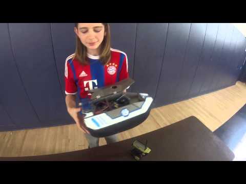

My intensive project is an RC Hovercraft based on this instructable by Dutch user Bauwser. My final design and execution deviated somewhat from his, but the overall idea remains the same. I didn’t have time to do any modifications (besides painting) due to my shortened time at Bluestamp, but I was able to get it off the ground (literally) and flying. The electronics aren’t really that complicated– my receiver connects to the servo and speed controllers and the speed controllers then connect to both the battery (which powers the whole system) and the fans. There is a switch on the battery’s positive lead to turn the vehicle on and off. The body was designed in SketchUp and then laser cut in depron, and the skirt was cut from PVC-coated polyester. Though it was a bumpy ride at times, I am happy with my final product; through its construction I developed significantly as an engineer.
Documentation
Final Laser Cutting Plans Download
Bill of Materials
| Item | Vendor | Part Num | Quantity | Price | Link |
| 6mm Gray Depron – 10″ x 30″ | RC Foam | 10-905 | 1 (10 pack) | $10.00 | Link |
| 7.4v 2200mah battery | SparkFun | 11856 | 1 | $15.95 | Link |
| Nylon Hinges | Amazon | B0006O4FXS | 1 (6 pack) | $6.69 | Link |
| 18.5 oz PVC coated Polyester – 61″ Wide – Black | Universal Hovercraft | 157 | 1 yard | $12.95 | Link |
| 3-Channel Radio Transmitter and Receiver | Hobby Partz | 79P-GT3C-3Ch-Radio-LCD-Green | 1 | $54.00 | Link |
| Paracord | Amazon | Color: Black, Length: 10 Feet | 1 | $3.99 | Link |
| 30A ESC | Hobby King | F-30A | 2 | $9.99 x 2 | Link |
| 4750KV Brushless Motor 55mm EDF | Amazon | — | 2 | $16.93 x 2 | Link |
| Servo | SparkFun | 9347 | 1 | $13.95 | Link |
| Battery Charger | SparkFun | 10473 | 1 | $32.95 | Link |
| Insulated Crimp-On Bullet Connectors | RadioShack | 64-3047 | 2 | $2.49 x 2 | Link |
| Deans Connectors | SparkFun | 11864 | 1 | $0.95 | Link |
| Generic Toggle Switch | — | — | 1 | — | — |
| DC 12V 5A Power Supply | Amazon | 12V 5A | 1 | $10.78 | Link |
| Barrel Jack to Dual Alligator Clips Connector | Amazon | — | 1 | $6.99 | Link |
| MTN 94 Paint Markers 15mm | Flax Art | White and Electric Blue | 2 | $9.70 x 2 | Link |
Electronics Diagram

Second Milestone – Skirt & Test Drive
This milestone, like the last, took longer than expected. The creation of the new skirt went uneventfully– I was extremely careful this time and had everything planned and held in position with tape before getting the hot glue out. My very first test drive didn’t work very well; the weight was mostly concentrated in the back, but the airflow was designed to spread air evenly. I modified the airflow to favor the back openings and put a light skeleton in the back of the skirt. Problem solved. I was all ready to do my milestone video, but I decided to wait until the next day when I could use the gym and show a real test drive. A day later I went for a test drive off-camera before I was going to make this milestone video. The test drive went fine, but when I inspected the propulsion fan afterwards I noticed something worrying but expected– it was beginning to detach from its servo mount. Seeing as it was only held on by screws into some foam, I wasn’t surprised. I put off the video thinking that the repair would only take about 15 minutes and some hot glue.
Oh how wrong I was. I tried a few different methods, involving various screw, washer, and standoff contraptions (and a bent screwdriver– sorry Fred), and after a day and change I finally found a solution. I drilled into a washer, which I mounted onto my servo horn with three screws. The wires went through the washer, and the bottom of the fan was attached to the washer with epoxy. I wasn’t taking any chances, and this time it worked. I went out for another test drive–now without breaking anything–and was ready for this milestone. Just a few more weight and performance tweaks and some paint and I should be done (finger crossed).
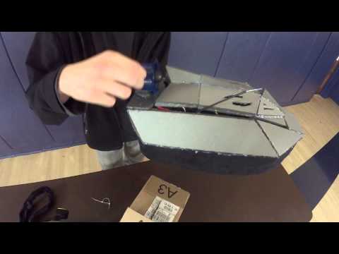
First Milestone – Body & Electronics

This milestone was meant to mark the completion of just the body, but with so much time spent waiting for parts and cuts for the body I had time to finish and install the electronics as well. It required a second iteration of the laser cutting plans (my prototype test-build out of MDF failed quite miserably), this time starting in a solid modelling program, but now the body is complete. As far as the body goes once the depron was cut assembly went smoothly– it was the electronics that required far more work. My first turbulence came when I realized that I needed connectors for my wires– you’d think an instructable might mention that, but it didn’t. Once they arrived though they were easy to solder and heatshrink. The bulk of my issues came with my transmitter.
First was the throttle– as soon as I hit the switch the fan went crazy. Turns out the remote was made for motors that go forwards and backward; fans just go one direction. The “neutral” position was half throttle. So to fix my transmitter I took the whole thing apart and modified the trigger mechanism to use the entire range in one direction; problem one solved. Now my throttle worked, but my fan was still immensely more powerful than I wanted (blame Fred), so I had to figure out how to program my ESCs and transmitter to limit the throttle. My biggest and most recent trouble with my hover EDF (fan).
My channel three button, which I had assumed was a toggle switch, wasn’t working. Instead of turning on and off the fan would pulse on and make two short beeps on the first press and then emit two more beeps on the second. To the internet! Nothing. So I decided to make a forum post of my own. On said forum post a man named Steve recommended that I plug a servo into channel three and see what happens. Out of options, I obliged. Steve and I assumed that it would do one of two things– toggle on and off and leave me even more confused, or stay on for the duration that I held the button. Neither happened; instead the servo alternated full throttle and full reverse. I had an idea, if I tuned one of the end points to 0% then it would be full throttle and off… right? Indeed it was. So all of my electronics worked. It took some effort to stuff them all into the body, but it was mostly uneventful. It did take a while for me to stabilize the back fan. And here we are, milestone one. I should be back soon with the skirt for a test drive (flight?) in milestone two.

Laser Plans V.2 and Solid Model

The Beginning
Theory
In short, a hovercraft is a vehicle (technically an aircraft) that travels on a cushion of air. This air cushion is often contained by a skirt, allowing it to become slightly higher pressure than the air surrounding the craft. This pressure difference is what generates the hovercraft’s lift. There are three common skirt designs– the bag skirt, the wall skirt, and the finger skirt. Each has its advantages and disadvantages, but for this project I decided that the wall skirt, being the easiest of the three to fashion for a non-circular craft as well as quite hard to damage, was the best choice. Next, the material; here Depron was the obvious decision. Sturdy and light even by foam standards, it will allow me to create a solid, many-layer body that still weighs next to nothing. The shape is relatively basic–a crucial factor for making the skirt–while still remaining quite aerodynamic and leaving room for all the necessary electronics. Though I mostly followed the design of the instructable, I made a few key changes in my design, particularly regarding the positioning of the hover fan. For easiest and cleanest assembly I will laser cut my design, and then put it together with hot glue. Though there are lighter glue options, hot glue is quick and easy; the weight gain is not enough to be worth the extra effort.
Body Design V.1

Note: Detailing is not entirely finished/designed yet, and airflow layer will receive slight modifications due to removal of second lift fan.
Laser Cutting Plans V.1
Red is cutting, blue is etching

Starter Project: MintyBoost

My starter project was the MintyBoost kit– a portable, AA battery-powered USB charger. It was my first real exposure to soldering, but I learned quickly and it went mostly without incident. The circuit contains four capacitors, two bypass (ceramic) and two electrolytic, each with the purpose of smoothing out voltage changes. Similarly, there is an inductor that smooths out current changes. There are also have a few resistors in order to lower the flow to match the needs of the boost converter. Once the current and voltage are smoothed the electricity goes two places– to the boost converter and to the central two USB pins. The boost converter raises the 3V current provided by the two 1.5V batteries in order to satisfy the phone’s 5V needs. Finally we come to the USB female jack. USB ports have four pins in them, the outer two are for power and the middle two are for data. We supply the five volts from the boost converter to the USB power-in pin, and the ground signal to the power-out. The data pins are more complicated. To charge most devices you only have to provide them with power, but for Apple portables you need to handle the data pins as well. This is because Apple devices are courteous– they ask for permission to take a certain amount of power instead of just taking it. All we need to do then is to constantly give it the go ahead signal, which happens to be about two volts. So with a few resistors we can use the diverted electricity to tell the iPhone that it is good to go.
Video
Schematic
