Video Game Emulator
There are four major components to the Video Game Emulator: the Raspberry Pi, the battery pack, the project box, and the monitor. The Raspberry Pi is a mini computer that can be used for a variety of tasks, such as a video game emulator, and the monitor displays the functions of the Pi. With this setup, I can play many older games as long as they have ROMs, such as Super Mario Bros. The battery pack allows the device to be portable, as it can power the pi and screen. The project box acts as a case to protect and make it easier to carry the raspberry pi.
Engineer
Zachary B
Area of Interest
Robotics and Software
School
Brooklyn Technical High School
Grade
Rising Sophomore
Second Milestone
For my Second Milestone, I made a casing for the device out of a project box. This casing allows the project to stay secure and for the multiple parts of the project to easily stay together. In addition, it also makes the device more aesthetically pleasing and structurally compact. I also added a battery pack to the device, making it portable, and a speaker giving it audio. In order to raise up the device within the project box, I had to 3D print 4 small boxes that the golden pegs from the monitor could rest on. At this stage I started adding more multiplayer games, such as Mortal Kombat, as I had received a pair of identical gamepads.
First Milestone
My First Milestone for the Video Game Emulator was setting up the system and making sure it worked properly. First, I attached heat sinks to the Raspberry Pi circuit board, plugged the Raspberry Pi into the monitor, and connected the HDMI jack. Then, I took a micro SD card and plugged it into my computer in order to install the RetroPi OS, and after two failed attempts using Etcher and Apple Pi Baker, I got it to work using sudo commands in the terminal. I put the SD card into the Pi and connected it to a power source. From there I used a flash drive to install games onto the device. The Raspberry Pi was now fully functional and could play games.
Original Hardware Setup(Before Modifications)
Starter Project
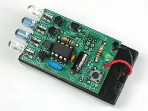
My Starter Project is the TV B Gone, a universal TV remote. When you point it at almost any TV, you can turn it on or off with the same remote. I enjoyed this project because I learned how to solder, assemble a circuit, and what parts such as capacitors, microcontrollers, oscillators, and transistors do.
How it works
The TV B-Gone is powered by two double-A batteries. The power flows through the battery pack and into the circuit board, and when the button is pressed, power flows into the capacitor. From there, it goes into the microcontroller, which is pre-programmed with almost all of the patterns a TV could use to turn on or off. The oscillator acts as a clock and keeps the patterns on rhythm, and then the pattern flows to the transistors. These black boxes act as a gate that allows energy to get to the LEDS at different times as dictated by the microcontroller, creating the infrared patterns that are cycled until all of the stored patterns have been used, and the TV turns on.


