
Welcome to my portfolio! My name is Vincent, and I am a rising senior at Chaminade High School. I love playing saxophone, tennis, and basketball in my spare time. I decided to go into the engineering major because I love math, science, and problem-solving in general. After learning a few things about Bluestamp, such as the cool projects I could finish within six weeks and the engineering skills students pick up during the Bluestamp experience, I joined the program without hesitation, and it turned out to be one of the best decisions I made!
The past six weeks at Bluestamp have been awesome! I have gained so much invaluable experience in programming and electrical engineering that I would not be able to learn at home. The process of frequently encountering problems and figuring out the most efficient way to solve them is grueling, but persevering through the obstacles and coming up with the final working product feels so satisfying and has deepened my interest in engineering. Coming into the program with almost no prior knowledge about engineering, I was able to complete the Pulse Sensor Wristband for my main project and the Voice Changer for my starter project.
My main project is a student defined project – the Pulse Sensor Wristband. It is a device controlled by the Arduino that detects heartbeats, displays a cardiogram, calculates beats per minute, and displays the current date and time on an OLED screen. The basic build plan is simple; it uses an Arduino Nano, a pulse sensor, an OLED screen, an RTC module, a 3.7V rechargeable battery, a boost converter, and velcro straps. The details of how I built this project will be explained in each milestone below.
Final Product: Pulse Sensor Wristband
Here are some pictures of the final working product:


Final Milestone
Here is the final video for my Pulse Sensor Wristband:

Since the 2nd milestone, I have made many improvements for my project. I made my Pulse Sensor wearable by mounting it onto a velcro wristband. I also added a mini Real Time Clock (RTC) module in order to display the current date and time at the top of the OLED screen.
In order to make the wristband, I used 2 types of velcro. I used the a 4″ sew-on velcro sheet for the base and attached a small strip of adhesive back velcro at the end of the sheet so I can adjust the tightness. I also used the adhesive back velcro to hold the battery in place on the bottom side of the wristband so it would not fall off. For the Minty Boost and the Arduino, I stuck the hook side of the velcro at the bottom and attached them onto the loop side of the wristband. And now the device is held in place nice and tightly.
To display the date and time, I used the mini RTC module for Arduino. It took me a very long time to finally solder it to the rest of my device and make the OLED display the time. The mini RTC actually came with a bulky female header, so I had to first cut off the plastic piece, and then desolder the pins from the board. I had to be extra careful and precise because all the connections were really small, and one small mistake can easily short circuit the IC chip and destroy the RTC. After I finished desoldering, I then had to solder the RTC onto my protoboard next to my Arduino, which was also very time consuming. The code for the RTC was the most difficult part for me. After conducting some research on the libraries for the RTC modules, I found one that fits my project and incorporated it into the rest of my code. So now the OLED screen also displays the current date and time!

Originally, my idea for the main project actually was to build an iPhone Stethoscope. It is essentially a stethoscope with a microphone attached at the end of the stethoscope tubing. The microphone will pick up the heartbeats whenever the heart contracts and transmit the signals into the iPhone using a TRRS plug. The iPhone can then monitor the heart rate and come up with a cardiogram by using the iStethoscope application in the App Store. But then I realized that this idea is very impractical because the stethoscope plugged into the iPhone would end up too bulky to carry around, and it can be easily outmatched by any applications in the app store that can pick up heartbeats with the iPhone itself without using a stethoscope hardware. After pondering through some solutions, I decided to accomplish the same goal with a smarter and cleaner approach by building a stand-alone pulse sensor that can be worn on the wrist, so that people can carry it around much more easily if they want to monitor their heart rate, which evolved to become my project now.
Schematics:


Code: Pulse Sensor Wristband Code
Source Codes Used:
- BPM calculation: https://github.com/WorldFamousElectronics/PulseSensor_Amped_Arduino
- OLED waveform: http://arduino-er.blogspot.com/2015/04/display-waveform-on-mini-oled-with.html
- RTC: http://giltesa.com/2012/09/02/libreria-gds1307-para-rtc
Bill of Materials: Pulse Sensor Wristband – BOM
Second Milestone
I have just reached my second milestone! Here is my second milestone video:
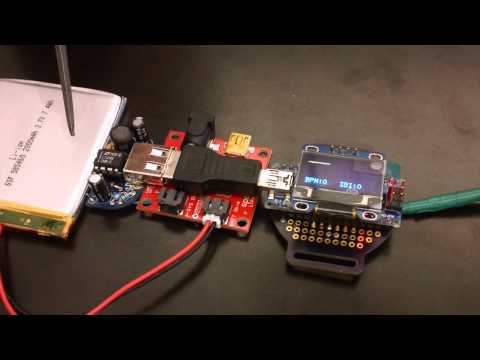
In this milestone, I took the basic device from the first milestone and made many improvements on it, so it can be mounted on a velcro wristband. I was able to give it portability by adding 3 important features to it: a 3.7V rechargeable lithium ion battery, a boost converter, and a charging circuit for the battery. In order to minimize the size, I soldered the Arduino Nano onto a piece of wearable protoboard, raised the OLED screen up to sit right above the Arduino by using male – female headers, and placed the charging board underneath the mini USB jack that connects the Arduino to the boost converter.
Here is a picture of the front and back sides of the device:

I decided to use the 3.7V lithium ion battery because I wanted to make sure that the battery is thin enough to be worn on the wrist but still powerful enough to run the system. I thought about using 9V batteries first and connecting it to the Arduino’s internal linear regulator to step down the voltage. But I realized that these batteries are very thick and bulky, and they are known for having short battery lives. Also, connecting an Arduino to a 9V battery is very inefficient because almost half of the power is dissipated as heat in the linear regulator in order to step down the voltage. I would not want to have to charge my wristband every 4 hours, so 9V batteries are out of the question. After looking at a few other batteries, I chose to use this 3.7V battery with 2000 mAh to have a longer battery life. But since the Arduino operates at 5V, the 3.7V input is simply not powerful enough. So I decided to use a boost converter to step the voltage up to 5V. The boost converter I’m using is the minty boost from Adafruit; it takes voltage inputs as low as .7 V and provides a steady 5V output. And here is how it works:
The system relies on the inductor’s property to resist changes in current by changing its voltage. Inside the boost converter chip in the middle, there’s an internal switch that is switching on and off very rapidly. When the switch is closed, the circuit is shorted so that there’s more current flowing to the inductor. The inductor then stores up some charge by creating a magnetic field. When the switch opens, the inductor has to raise its voltage to keep the current flowing because of the higher resistance in the output. Also, when the switch is open, some charge is stored in the 2 electrolytic capacitors so that when the switch closes again, they can provide the voltage for the output. This process has to happen very quickly so that the inductor and the capacitors don’t discharge too much. In the circuit, the switching rate is what determines the amount of charge stored in the inductor. It is controlled by the IC chip so that there’s always a 5V output. The Schottky diode makes sure that the current only flows one way from the battery to the USB. It has a smaller voltage drop than normal diodes so that the system is more efficient. And finally, the 2 ceramic capacitors make sure that the output voltage is accurate and stable by filtering out high-frequency noise. Together, these components make sure that there is always a 5V output when there is a smaller input. The output of the minty boost is a USB port, so I used a male – male mini USB jack to connect it to the Arduino, which then powers the OLED screen to display the graphics.
First Milestone
I have just reached my first milestone! Here is my first milestone video:
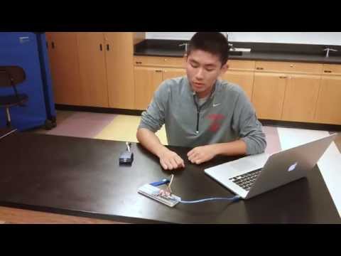
For my first milestone, I was able to wire the pulse sensor, the Arduino Nano, and the OLED display together on a breadboard, and perform the basic functions for my project. In this milestone, I currently power the Arduino from my laptop through a USB connection and upload code using an AVRISP programmer. When I put my finger on the pulse sensor, which is sewed onto a velcro strap to wrap around my fingertip, it can pick up my heartbeats and send the data to the Arduino, which then commands the OLED to display a cardiogram waveform and the calculated BPM (beats per minute) and IBI (interbeat interval).
The pulse sensor is a photoplethysmograph, which is a device that measures the changes in blood volume in the microvessels. It can pick up the amount of light reflected from the blood after shooting light through the skin. The pulse sensor I have uses a green LED as the emitter and a photodiode (which converts light into current) as the detector. When I put my finger on top of the sensor, the light from the LED shines through the skin into my blood vessels. During the systolic phase of the cardiac cycle, the heart pumps a surge of blood into the capillaries in my fingertip, and more light will be reflected back to the photodiode, causing a stronger signal. On the contrary, during the diastolic phase when the heart is relaxing, less light will be reflected, which will result in a weaker signal. The signal is then amplified by the operational amplifier inside the sensor so it is strong enough for the Arduino to pick up. The output of the of the sensor is connected to the Arduino’s analog pin A0. The reason I wanted analog instead of digital is that digital signals can only have two states, HIGH or LOW, in other words, ON or OFF, while analog signals can have a whole range of voltage values, which in my project I can use to graph a cardiogram. The Arduino then reads the signal coming from the analog pin A0 and uses that information to tell the OLED screen to graph a waveform and display BPM.
OLED screen when no heartbeats are detected: OLED screen when heartbeats are detected:


I encountered many problems while working towards this milestone. The first OLED was fried after 3 hours of testing when powered through the Arduino with 5V, and I still cannot figure out the reason. The most time consuming challenge which I had to overcome in order to reach this milestone was finding the most efficient algorithm for calculating BPM because I wanted to make ensure that the calculation would be accurate and consistent. Also, as a beginner in coding, I spent a full week on learning the Arduino programming basics and modifying the source codes to fit the needs of my project. I had to go through trial and error many times before getting rid of all of the errors and having all of the components function correctly. When I first fixed all the errors and tested the device, instead of displaying the BPM and IBI value, the bottom of the screen just displayed garbage characters. I later found out that I was using the wrong method to concatenate the strings and integers in the C language used by the Arduino. Once I correctly concatenated the types, it worked without a problem. I also encountered problems with the wires coming loose from the pulse sensor; I had to resolder the connections twice. To prevent the problem from occurring again, I used electrical tape, made sure that the connections are extra tight, and sewed the sensor onto a strap of velcro to stabilize it.
Code Explained
The code I used for this milestone consists of source codes from two different websites, which are hyperlinked below, as well as my own modifications and additions. First, the PulseSensor_Amped source code calculates BPM with a very smart and accurate algorithm by finding the amount of milliseconds between each two beats, the Interbeat Interval (IBI), and dividing 60,000 milliseconds (1 minute) by the IBI. The divisor IBI is calculated by the average of the 10 previous IBIs to get a more consistent BPM value. The algorithm also sets up Timer2 within the Arduino, which enables an interrupt to check every 2 milliseconds if there is a heartbeat to ensure accuracy. The process starts when the Arduino reads the A0 pin and receives a signal. Every time the signal surges up the threshold value, there is a beat, and when the signal drops below it, the beat is over. There is much debate on when exactly a heartbeat starts in order to calculate BPM, but conventionally, the start of a heartbeat is placed at 50% of the upward rise in the signal surge, which is used by this particular source code. The second source code is from Arduino_er; it uses the u8g graphics library and displays a waveform on the OLED screen by mapping out the amount of voltage received on the A0 pin and connecting the pixels. Finally, I tweaked the codes to make sure that the cardiogram, BPM, and IBI info are displayed on the OLED instead of being sent to the serial monitor, as it was in the original source code. I also made sure that whenever the pulse sensor is not sensing any heartbeats, the BPM and IBI are 0.

Source codes:
Start of heartbeat reference:
Starter Project: Voice Changer
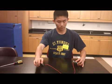
I chose the voice changer as my starter project. Since I have no previous experience with soldering or even engineering in general, the project seemed overwhelmingly difficult at first. But after conducting a little bit of research, I was able to follow the manual step by step and assemble the parts together. When I finally finished the project on my third day after solving many problems, I felt very accomplished and satisfied with my work. Here is a video of my voice changer:
Soldering was a very tedious and awkward process for me during the first day because it was my first time learning how to do it. But as I familiarized myself with how to correctly handle the soldering iron, I was able to speed up the process tremendously. Learning the names of the parts and their functions presented me some problems as well because I had never before seen resistors or capacitors.
I encountered many problems during this project. On the first day, I burned off a copper ring on the PCB when I was soldering. I compensated for the mistake by scraping the PCB and exposing more copper next to its original spot. When I finished soldering all the parts onto the PCB and test ran it on the second day, it did not function properly; it made loud noises whenever I turned it on. I tested the connections with a DMM and found three short circuits that resulted from poor soldering. I thought that the problem also existed because the speaker was too close to the microphone, so it was receiving too much feedback. I finished fixing these problems on the third day, and it functioned properly, but a small amount of noise could still be heard when the power was on. I finally replaced the wire on the speaker one more time with a much longer one, and it finally functioned well at the end.
Here is how the voice changer works. The battery provides the voltage needed to run the device. The resistors help restrict the current flow in some areas to make sure that the circuit will not burn out. The microphone picks up the signal, which is modified by the microcontroller when different buttons are pushed. The capacitors help filter the signal, which is eventually transmitted to the speaker. Finally, the speaker translates the signal into the sound with the desired effect.
By doing this starter project, I learned a lot about soldering and circuits fundamentals. It was overall a very gratifying and valuable experience.