
Vinay’s Bluestamp Experience
Hi, my name is Vinay and I’m a rising sophmore at Lynbrook High School. At Bluestamp, I will be working on the SparkPunk SoundKit as my starter project and a 3D printed bionic hand that detects myoelectric signals to function.
Intensive Project
Milestone III and Final Video:
In my final milestone, I added the myoelectric sensors and made the hand respond to the impulses sent from my hand. By taking advantage of EMG signals that are created when flexing a muscle, I measured and analyzed the detected voltage readings of each finger in order to make the robotic prosthetic more dexterous and responsive. The brain of the prosthetic is an Arduino microcontroller and an electrode sensor manages the data signals from electrodes on the forearm. The muscle sensor collects a stream of input and rectifies using ADC (analog to digital converter) making it easier for the Arduino to process. When contracted each finger generates a voltage spike. This data when plotted on a graph resulted in a parabola. During testing, it was evident that each finger generates a specific voltage range and has a different voltage maximum. In order to make the detection more accurate and efficient I wrote an algorithm that detects each finger’s movement separately and also eliminates noise and small changes in voltage levels. When the signal reaches the limit determined by the algorithm it powers the corresponding motor in the robotic hand.
Some of the complications, I had were discovering the threshold value. After figuring out that this depended on electrode placement and tuning the gain on the electrode sensor, I was able to find the optimal position of the elctrodes: one in the middle of the muslce, one on the end, and finall one on the bone.
Milestone II:
I have finished my second milestone, which was to complete the entire hand with the thumb and servo. The picture below shows the two halves that were screwed together with four M3 bolts. On the back half we have the four fingers all together in the arrangement of a human hand. On the front half, the thumb, its motors, and a servo that moves it in and out are all mounted. You may have noticed that the thumb is constructed differently than the other fingers. The thumb is similar to the other fingers in the sense that it has a spool and two ball bearings. However the motor is actually separate from the entire thumb housing. The threads run through cut-outs in the thumb housing so when the thumb moves in and out it doesn’t rub against anything.

Even in the construction of the thumb and putting together the hand, I had some major problems with the code as well as the build. One problem I had was getting the servo to fit into the thumb housing. In the STL file which I used for the print there was an opening but when it printed there were layers of unwanted infill. To solve this problem I used the dremel to clean out the slot for the servo and I shaved off the ends of the servo itself to get flush enough to print.
Another problem I had in the build was getting the servo to align properly and be vertical with the axle in the top. Originally the servo was at angle and this put a lot of stress onto the servo. At one point the turning head had actually bent and refused to move. After fixing it with pliers I was able to get it to work. The picture below illustrates the solution. In order to get it to align I moved the hole that was needed to the left with a dremel.
The last problem I had was with the code. I had to restrict the motion of the servo because I did not need the full 180 degrees of motion. Also whenever I plugged in the servo it moved really fast to an upright position and it stalled. To address this problem, I learned how to use the servo.attach function which allows you to initialize the servo the right position every time you plug it in. Also in order to slow down the motion and restrict the motion, I learned how to use a for loop which uses a delay of 15 ms to slow down the rotation of the servo as it goes through each degree.
Milestone I:
In my first milestone, I have completed the four finger (the thumb is still under construction). These four fingers are controlled by the 2 adafruit motorshields that are stacked on top of one another to get access to the 5 DC motors that I need for each fingers. The picture below shows you the different parts of the finger.
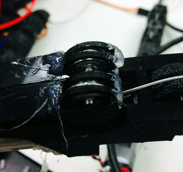
Within each of the joints of the finger there are ball bearings on dowels that allow the finger to bend smoothly. The two parts that are in blue are the ball bearings and spool, which is mounted directly on the motor. A steel coated nylon thread in through the spool, with the spool halfway. Each half of the thread is run through a ball bearing and goes through either the top or the bottom of the finger. When the spools spins it releases thread one way and pulls thread in the other, making the finger bend. Threading the fingers is a complicated process that requires patience and a delicate hand.
Finishing these fingers were a huge challenge as I didn’t have the exact same pieces that were needed such as the ball bearings. This meant that I had to be creative and solve these problems with the materials I had on hand. Even though the printed pieces were from the files that were given by the instruction, I still had to do some sanding in order for the parts to fit securely together. The tensioners in the motors which would be using grooved ball bearings as winches was a big problem. The groove ball bearings that I needed were only found in China and would take 4-6 weeks to ship which was not possible. A good thing though was I had extra flat ball bearings so I brainstormed some ideas as a solution.
- Use washers in a big-small-big arrangement in order to create a g
 roove.
 - Use a flanged ball bearing with a washer
- Design a pressfit cover for the ball bearing to 3d print
- Design a ball bearing and 3d print it
 roove.
After designing the last two ideas on Autodesk Inventor as they were an option, I went ahead and printed them out. The other two ideas would be hard since it would require specific dimensions that would be hard to find. I soon found out that the printer was having trouble getting the tolerances right on such a small piece like a pressfit. The ball bearing on the other hand would be a backup option but the only problem as that it would not be as smooth as the ball bearing. I decided to build one finger and make the best choice when the situation comes. After using the regular flat ball bearings I brainstormed some more ideas on how to keep the string on the flat ball bearing rather than making a new ball bearing. I came with ideas like:
- Rubber Band Guides
- Washers that go around the bearing
- Soldering guides on the ball bearing
- 3D printing guide rails
I did some designing and I printed out some prototypes for the guide rails that would be glues to the tensioners and would “float” over the surface of the ball bearing and make sure the string stays on top of the bearing. This was a challenge in gluing it down with hot glue but after some trail and error, I managed to come up with a way that would not let it slip off.
However the fingers were not the only major problem, I had just found out that the motor controller that I was using was not compatible with the new stacking features since it was using an older version of the adafruit library. Usually when stacking boards you use an I2C bus which allows for addressing by soldering logic panels. Because of this I had to trade my second Ossep shield that I had bought with another student for the adafruit shield. I thought I could solder a new address to the new one and so the boards could work together. The new stacking feature is a part of the new library of the version 2 of the adafruit library. However the libraries would not work together since there were multiple redefinition of commands ex. (microstep functions). From there I had two option either get a new shield or merge the libraries. I realized the merging idea would be really hard because I would have to change the syntax for one of the libraries.
Starter Project
SparkPunk Sound Generator Kit

My starter project is a sound generator kit which is like a mini synthesizer and outputs the sound through a headphone or speaker. It has 4 switches which play 4 different sounds and potentiometers allow us to change the frequency of these sounds. The resistors are key as they pull down the current to ground quickly when the current is not needed or in this case when there is no sound playing when the trigger is pressed. Capacitors store energy so when I need a lot of electricity at once, like to start the sound, I don’t short the circuit and control the tune. In this circuit there are 7 electrolytic capacitors that are polarized and store more energy. Diodes control the direction in which the current flows. In this case the IC unit (integrated circuits) acts as an oscillator that controls the pulses for the frequency of the sounds. All of this is controlled by a 9V battery that plays the sounds when the trigger is pressed. I chose this project as it was a good challenge for soldering as it has many resistors, capacitors, switches, and diodes. It also has many modification areas such as adding photocells, soldering a speaker, or adding connection to mix sounds as well. Overall this was a fun kit and I recommend it.
