For my project, I built a robotic hand. I used a 3D printer to create the frame for the hand, and servos to move the fingers. Then I used a glove equipped with flex sensors to control the hand.
Engineer
Trevor H
Area of Interest
Electrical Engineering
School
Marin Academy
Grade
Senior
Reflection
Before BlueStamp, I never felt confident in what I was building. Whenever I had to write code, I always thought it would fail. However, after my time at BlueStamp, I feel like I have a better understanding of coding with Arduino and am more confident in what I write in my code. This happened when I was working with the voice control module because the code I wrote worked instantly when I uploaded it to the Arduino board. This was possibly one of my favorite moments of making this project because I was blown away by the fact that it all worked perfectly. I also am more confident and better at making circuits. I always used to use a breadboard to make circuits. This made it easy to correct mistakes, but now I feel better about soldering circuits together. This is of course after I incorrectly soldered multiple leads together that should have been connected and had to desolder then solder a large portion of my circuit. I think this newfound confidence in what I create will help me create more and allow me to work on harder projects. Perhaps in the future, I could make an entire arm rather than just a hand. Also throughout my time at BlueStamp, the guest speakers have given me insight into entrepreneurship and what it takes to actually create a product rather than just complete a project. Further modifications for this project could be making the glove wireless, so you are not stuck having the hand and glove connected. I tried this, however, my design and code made it so each servo would detect every other flex sensors rather than just the one corresponding to the proper finger.
If you are thinking about building this project you can find my bill of materials here, my code here, and my build plan here.
Final Milestone
For my final milestone, I made the hand voice controlled. The voice control works by using a shield for Arduino. Shields are devices you can place on an Arduino that give it more sensors, such as temperature sensors, Bluetooth sensors, etc. The shield I used is called 1sheeld. 1sheeld connects an Arduino board to your phone allowing the board to use all the devices in your phone as shields. So I used the phones voice recognition software. Voice control works by converting the analog waves created when you speak into a digital format. The difference between analog and digital signals is analog is made of sin waves while a digital signal made up of square waves. Then it breaks up the word into multiple parts known as phonemes. Finally, it compares the phonemes and to a dictionary and sends the word it believes to be most like the one you said. It then sends the word to the Arduino, which then checks if the word is a command. If it is a command the Arduino will then move the fingers to the position that the command tells it to.
My second milestone is the completed hand. The hand has two strings run through the front and back of each finger. The one in the back holds the finger up when the line is tense. The string in the front pulls the finger down when it is pulled. The strings were the main part of creating hand and took up the most time. The first issue I had was the string I was using. After I had tested it on one finger I determined that it wasn’t strong enough to pull the finger back up. However, I was able to find a wire that worked as a string for the hand, and later brought in some fishing line that worked even better. Another major problem I faced was the string couldn’t seem to stay tense. I asked for help from another person working on their own robotic hand, and I learned that I needed to have two separate strings going through the hand rather than one long continuous string tied to itself at one end. One of the smaller problems was getting the wire through the hand. It was difficult to push it through because it could easily get caught on something, so I used solder to help.
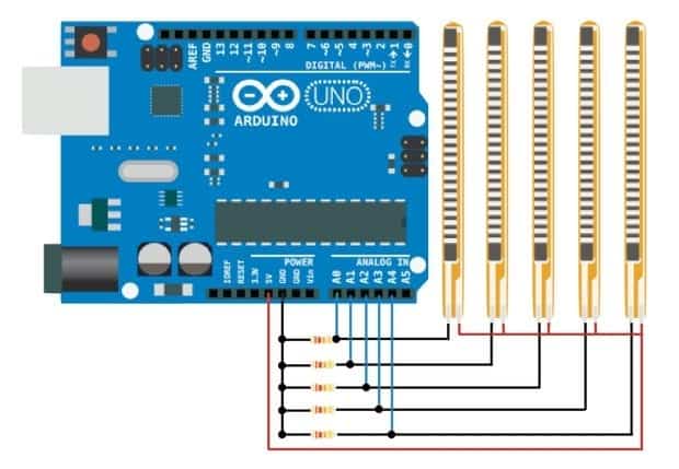
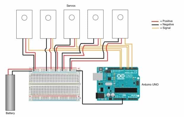
My first milestone is the completed control glove. This glove is used to control the servos that move the fingers. This is possible through flex sensors. When the flex sensor is bent the resistance increases. The resistance increase because the flex sensor is printed with ink that has conductive particles in it. Therefore, when the sensor is unbent the particles are closer together which creates less resistance than when they are bent and farther apart. This increase is detected by the Arduino which takes the analog signal and outputs a digital signal from a pin that was assigned to the analog input. This signal will tell the servo to move a certain amount corresponding to the amount of resistance the flex sensor is creating. Below are images of the flex sensor circuit and the servo circuit.
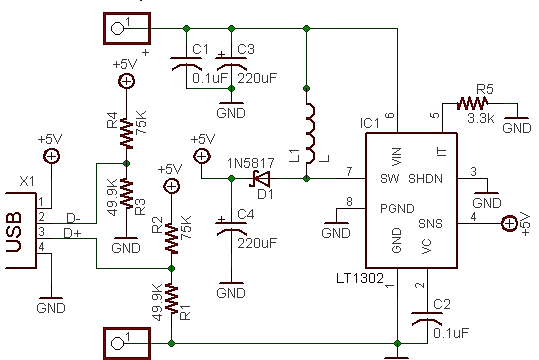
For my starter project, I made the Minty Boost which is a charger for your phone that uses AA batteries. The Minty Boost works by converting the batteries’ 3V to the necessary 5V required to charge a phone. It is able to accomplish this by using an LT1302 chip and an inductor to convert the voltage. The inductor is a coil of wire that takes in power stores it, and with the help of the LT1302, it is able to boost the voltage. There are also multiple capacitors in the circuit. The 2 yellow capacitors are .1 microfarad capacitors and are used to stabilize the LT1302 and the output voltage. The other two 220uF capacitors are used to smooth the voltage. Under the chip, there is a 3300 ohm resistor that is used to improve the high current capability by connecting the 5th pin of the LT1302 to ground. The other resistors all change the current so that it is the correct amount of amps to charge a phone. There is also a diode which ensures that the current is going from the battery to the USB port. Below is a schematic of the Minty Boost v3.


Awesome!!!