
Solar Panel Sun Tracker-
Phone Charger
Engineer
Tiffany D
Area of Interest
Psychology/ Environmental Engineering
Grade
Incoming Senior
School
Galileo Academy of Science and Technology

What it is:
The purpose of this project is to convert sunlight into energy utilizing solar panels and using the energy to power your phone. The solar panels are able to rotate back and forth and track where light is most present, maximizing the amount of sunlight absorbed.This enables more energy to be converted to power your phone.
What inspired me:
I loved the idea of incorporating renewable energy into engineering. I’ve always been interested in Environmental Science so integrating both these things together amazed me. I specifically chose this project because I know as technology is constantly growing and becoming more essential to our lives, we will depend on them more. This means more energy needs to be used to charge these devices. I hope with this project, I could inspire others that renewable energy could be used as an alternative. Not only for powering a phone, but for anything.

First Milestone
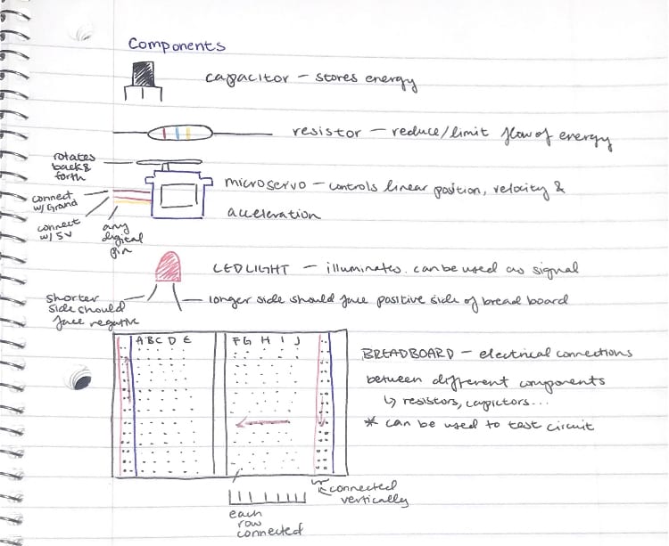
Getting familiar with the components:
By drawing and labeling a few of the components, I can identify them easier and gain a better understanding of what each does. Doing this can help me recognize how each factor come together to achieve the final result.
Getting the micro servo to spin:
My first milestone was getting the micro servo to spin using the arduino UNO. After constructing the model, I put in the code for the servo to rotate in a loop from 0 to 180 degrees. However, when I tried to upload the code onto the Arduino Uno, errors kept occurring. I was confident in my model so I tried inputting different codes, restarting my computer, switching to different ports–but nothing seemed to work. I was so focused on my computer I didn’t think twice on checking my model. After numerous attempts, I decided to restart from the beginning. That’s when I realized I had switched the brown and red wires, connecting the brown with 5v and the red to Arduino Ground. When I fixed this issue, the micro servo automatically started spinning.
I learned to never overlook the little things, even when you feel confident in them. The smallest mistake can be the root of the problem.
How this contributes to the project:
The micro servo will be connected to the solar panels so as the micro servos rotates, the solar panels will rotate as well.
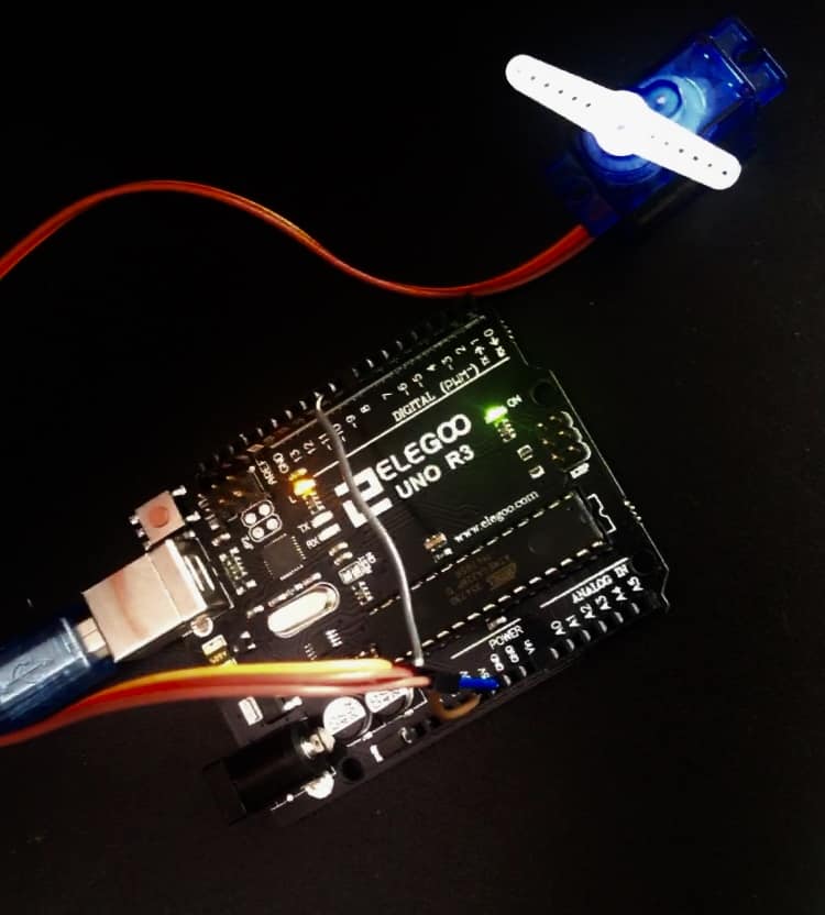
In the model above, the micro servo was successfully able to spin with the brown wire in GND, the red wire in 5V, and the yellow wire in D9.
Second Milestone
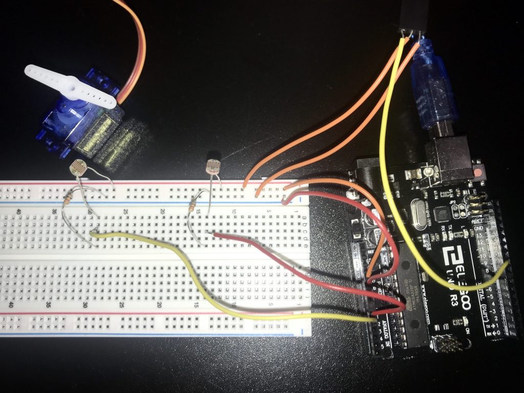
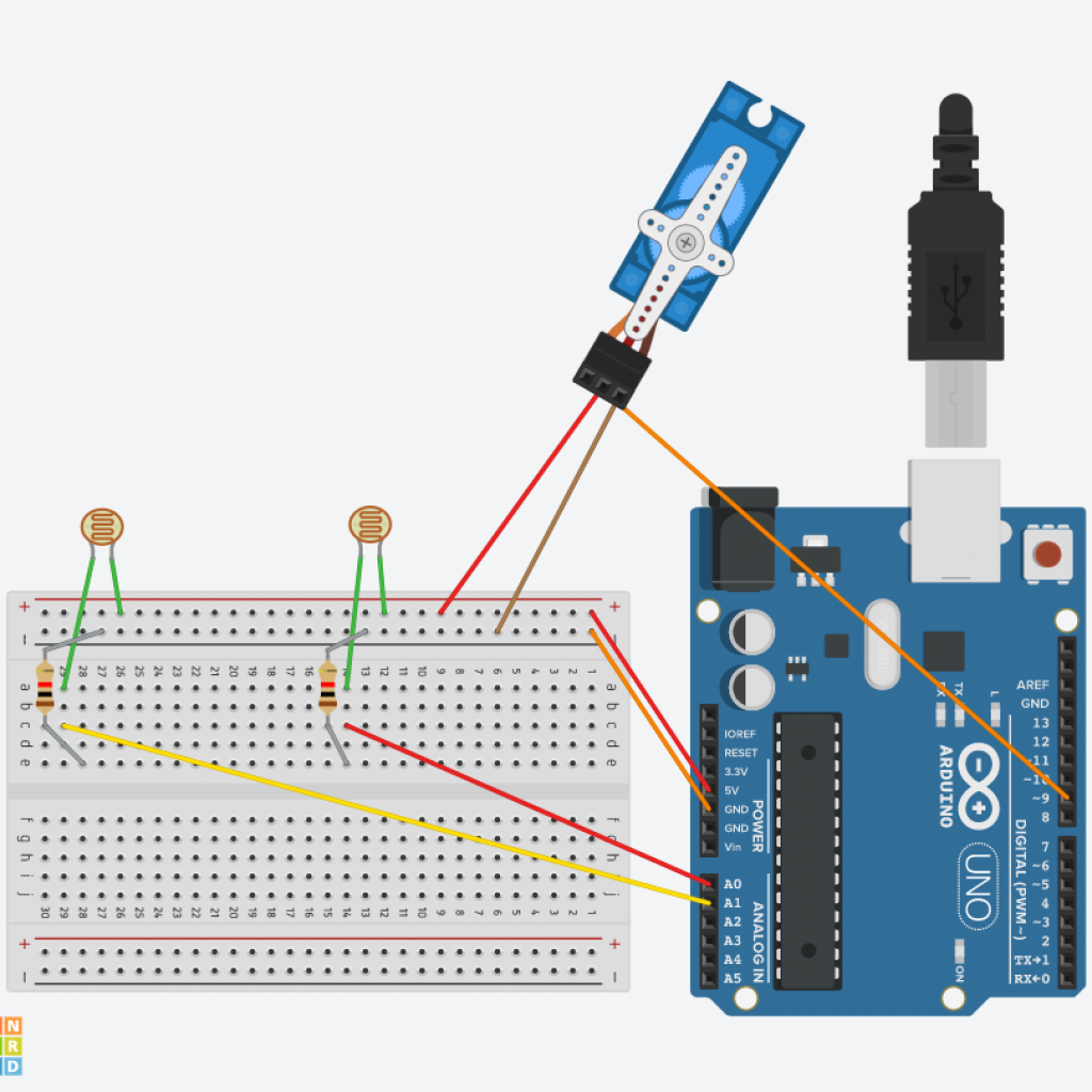
Getting the photo resistors to function & control the rotation of the the micro servo:
In my second milestone, I had to get the photoresistors to function as well as control the rotation of the servo motor. I had originally tried to follow a specific model in order to do this, but the exposed parts of the wires kept touching, causing issues: The micro servo wasn’t spinning, the photo resisters weren’t detecting light, the wires kept breaking. Nothing seemed to be functioning. After many unsuccessful attempts, I tried a different model. This again was frustrating because I kept flipping where the components were supposed to be, the wires kept coming out, and again wires were breaking. I thought this wouldn’t work again.
When I made sure all the wires were in all the way and in the correct placement, I uploaded the code and checked the serial monitor to test if the photoresistors were detecting any light. When I covered one of the photoresistors the number dropped drastically. I tested this multiple times and the numbers matched how much light there was. The photoresistors were detecting light!
I then altered the limit for the micro servo in the code so that it matched with my own. When I did this, the micro servo started to spin. When I covered one of the photoresistors the micro servo span clockwise, when covering the other photoresistor the servo span counter clockwise. I tested this multiple times and the servo span depending on which photoresistor got more light.
//Sun Tracker Sketch
//
//This sketch is designed for use with a 9gram servo, able
//to be powered directly from the Arduinio without an external
//power source. For fritzing diagram, see Github repository
//https://github.com/nickalanf/Arduino–Projects
//The Serial monitor section is for debugging purposes, or for general interest,
//one once the device is functioning correctly, can be diasabled
//
//Sketch by FIELDING – 8/2/18
#include <Servo.h>
Servo servo; // Create a servo object to control the servo
int eLDRPin = A0; // Assign pins to the LDR’s
int wLDRPin = A1;
int eastLDR = 0; //Create variables to store to LDR readings
int westLDR = 0;
int difference = 0; //Create a variable to compare the two LDR’s
int error = 10; // Variable for is there is a noticable difference between the tow LDR’s
int servoSet = 140; //Variable for position of servo – will be different for each device
void setup() {
servo.attach(9); //attaches the servo object to PWM pin 9
Serial.begin(9600);
}
void loop() {
eastLDR = analogRead(eLDRPin); //Read the LDR values
westLDR = analogRead(wLDRPin);
if (eastLDR < 200 && westLDR < 200) { //Check to see if there is low light on both LDR’s
while (servoSet <=140 && servoSet >=15) { // if so, send panels back to east for the sunrise
servoSet ++;
servo.write(servoSet);
delay(100);
}
}
difference = eastLDR – westLDR ; //Check the difference
if (difference > 10) { //Send the panel towards the LDR with a higher reading
if (servoSet <= 140) {
servoSet ++;
servo.write(servoSet);
}
} else if (difference < -10) {
if (servoSet >= 15) {
servoSet –;
servo.write(servoSet);
}
}
Serial.print(eastLDR); //Serial monitor can be useful for debugging/setting up
Serial.print(” – “); //Use it to see if your LDR’s are noticeably different when
Serial.print(westLDR); //They have equal light shining on them, if so, correct with the error value
Serial.print(” – “);
Serial.print(difference);
Serial.print(” – “);
Serial.print(servoSet); //Fine tune the servo settings, to maximise swing available
Serial.print(” – “);
Serial.println(“.”);
delay(100);
}
Third Milestone
ATTACHING THE PHOTORESISTORS ONTO THE SOLAR PANELS:
I attached the 2 photoresistors on the solar panels utilizing hot glue, one on the east side and one on the west side of the solar panels. After that I used jumper wires to connect the photoresistors onto the breadboard, putting them in the same placement as before. I made sure they were long enough so the solar panels could move back and forth when mounting it on a support beam. When I made sure all the components were on the breadboard, I uploaded the code again to see if it would function.
The micro servo automatically started spinning and as I shined a light on the photoresistor it spun in the direction of which photoresistor had more light.
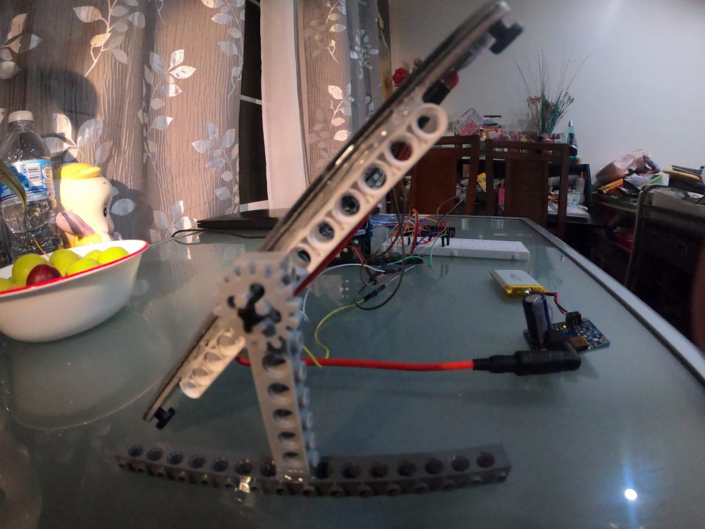
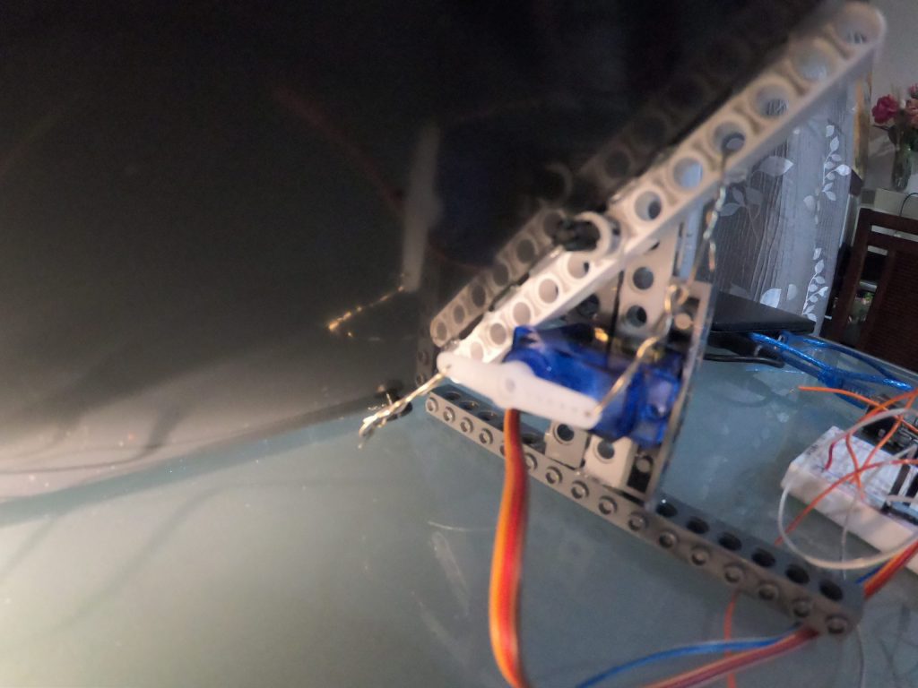
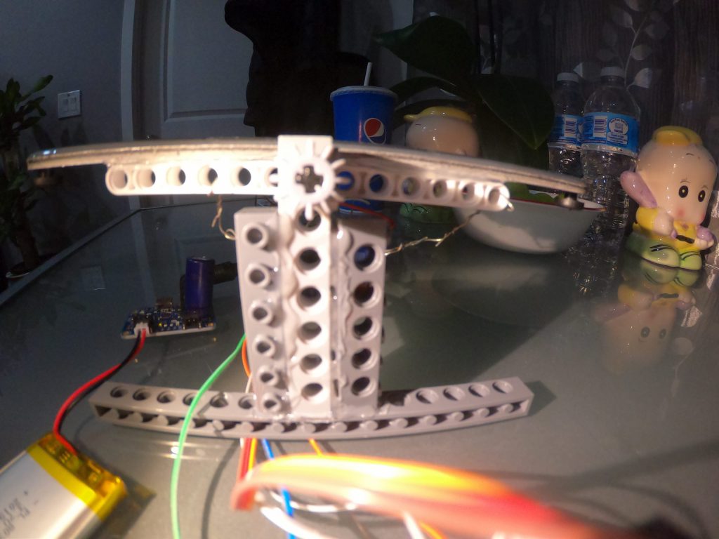
BUILDING THE FRAME:
I hot glued some lego pieces together to make a stand, while also connecting it to a piece that could spin back and forth to the solar panels. This enables the solar panels to rotate smoothly and efficiently. I then attached the micro servo to one side of the stand and attached stripped wires from the micro servo to the solar panels. The stripped wires will be able to pull the solar panels in the direction the micro servo is spinning.
When connecting the micro servo to the solar panels utilizing the stripped wires, it was difficult to get the solar panels to rotate all the way. When making the stripped wire too tight, it restricted the movement when rotating the other direction. However, if it was too loose, it wasn’t strong enough to pull the solar panels. I had to balance those out in order for the solar panels to rotate smoothly.
PHONE CHARGING:
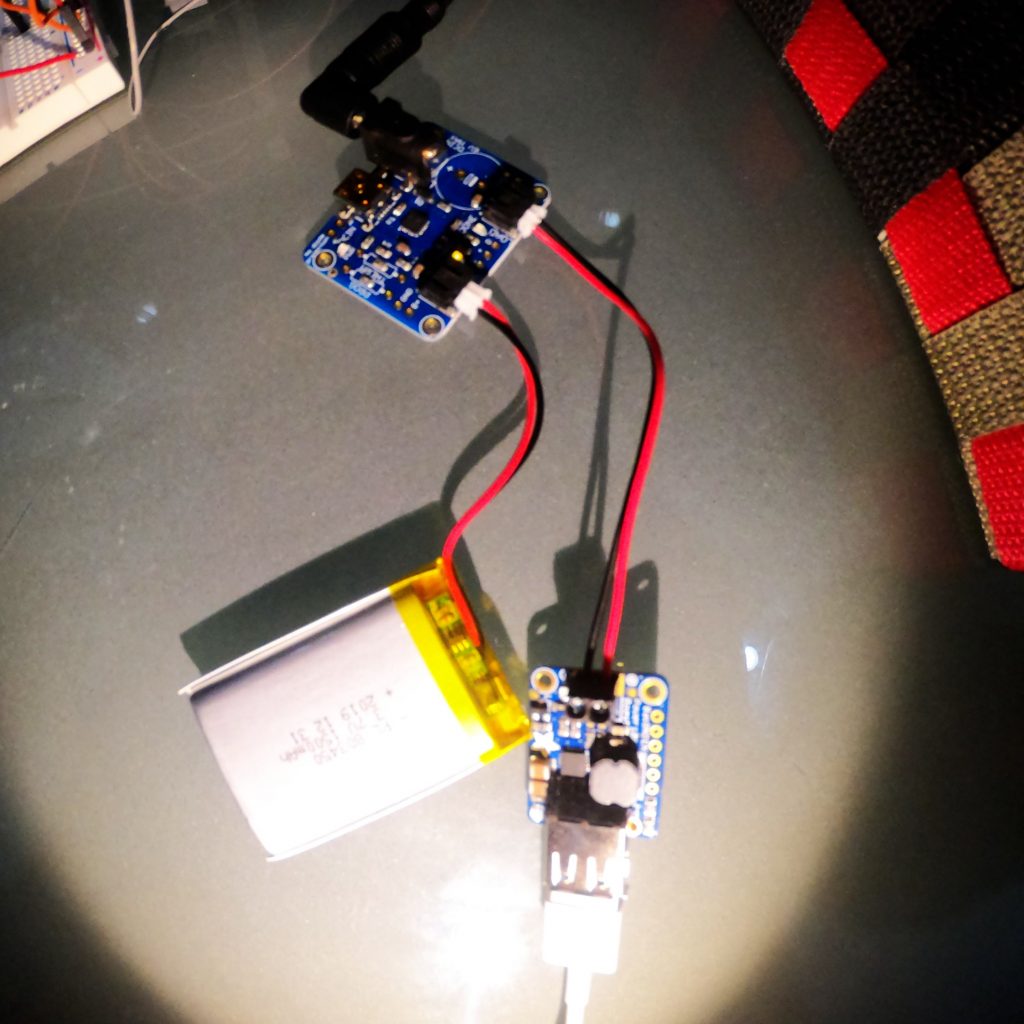
On the back of the solar panel there is a red wire I connected with a capacitor. This capacitor is able to store that energy from the solar panels and charge a battery–this battery can then be used to charge a phone.
The capacitor connects to a lithium battery and a power boost 1000 basic. The battery gives out 3.7 volts, but a phone needs 5 volts in order to be charged. With the power boost 1000, it takes that 3.7 volts from the battery and gives out 5 volts, enough for a phone to be charged.
Reflection:
I thought this experience was very challenging as I didn’t know what I was doing most of the time, but when I did do something right that feeling was one of the best feelings in the world. It was like jumping in a pool without knowing how to swim and learning how to swim on your own. Although it was challenging, I learned that having no idea what you’re doing is okay because everyone starts off knowing nothing in the beginning. It’s about learning to be okay with that and still persisting. Even accomplishing the little things I was happy, but having this whole project functioning is absolutely astonishing. It has shown me that if I could build this project knowing nothing, others could do the same.
click here to see the solar panels rotate: https://drive.google.com/file/d/1Rl6ORWHy9MTj-U8vQKrn2QDvEujDjvIj/view?usp=sharing