Light Up Speaker
Hi my name is Tajjuddin Class of 2019. My main project is a light up panel that reacts to music.
Engineer
Tajjuddin M
Area of Interest
Mechatronic Engineering
School
NCA
Grade
Incoming Senior
Reflection
BlueStamp was a brand new experience for me. Even when I was tired and frustrated with my progress and losing hope, I always put my best foot forward. Being surrounded by many helpful friends working their hardest pushed me to do the same. I also worked my hardest and I feel like I truly accomplished a lot. I learned what coding is and became great at soldering when I did not even know what soldering was. I plan to study what I learned here more and code small things to expand my horizon. I am honored to have had this chance to learn and experience. Thank you.
Final Milestone
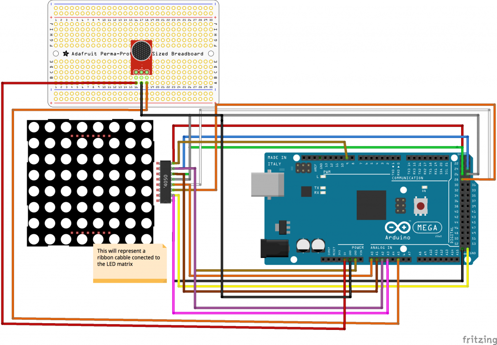
For my final milestone, I made my LED Matrix react to sound. The change in light pattern was shown on the matrix because of the Mic AMP from Adafruit (https://www.adafruit.com/product/1063 ). The Mic changes the amount of current supplied to the arduino based on sound waves. The arduino light pattern is based on the information it receives . The setup for the sensor is similar to the setup for the light sensor in milestone one. The changes were transferred through the code below by a ribbon cable.
RGBmatrixPanel matrix(A, B, C, D, CLK, LAT, OE, false, 64);
int sensorValue = 0; // variable to store the value coming from the sensor
void setup() {
Serial.begin(9600);
matrix.begin();
void loop() {
/ read the value from the sensor:
// sensorValue = analogRead(A5);
// Serial.println(sensorValue);
// delay(50);
/ Serial.print(” “);
/ Serial.println(numleds);
for (int i = 0; i < 64; i++) {
sensorValue = analogRead(A5);
Serial.println(sensorValue);
int numledslitup = map(sensorValue, 250, 400, 0, 36);
int colorchanger = map(sensorValue, 250, 400, 0, 7);
matrix.drawLine(i, 0, i, 32, matrix.Color333(0, 0, 0));
matrix.drawLine(i, 0, i, numledslitup, matrix.Color333(colorchanger, 0, 7 – colorchanger));
delay(10);
}
}
// Input a value 0 to 24 to get a color value.
// The colours are a transition r – g – b – back to r.
uint16_t Wheel(byte WheelPos) {
if (WheelPos < 8) {
return matrix.Color333(7 – WheelPos, WheelPos, 0);
} else if (WheelPos < 16) {
WheelPos -= 8;
return matrix.Color333(0, 7 – WheelPos, WheelPos);
} else {
WheelPos -= 16;
return matrix.Color333(0, WheelPos, 7 – WheelPos);
}
}
The code above made this all possible. It programmed my Mega to control the matrix and the order to put many lights in. I made the matrix react quicker by lowering the delay to 10 milliseconds. The biggest troubles I had was when I had to rewire and take apart just to rebuild the code was one of my greatest struggles. Although I was annoyed by the constant rewiring it taught me to be better as a mechanic. I am now pleased to announce that this is the end of my bluestamp project, thank you.
For my second milestone, I had the LED Matrix to react to light. To have the matrix react to the light, I used a photocell. A photocell is a resistor that changes resistance depending on how much light is on it. I connected the photocell to a breadboard which wired to the same Arduino Mega setup from milestone one. Down below in figure one, you can see my full wiring diagram.
To make it reactive, I first had to put the photocell into the code. I first made a valuable to store the value of the senor in my mega and I used the A5 wire to transfer the data. Here’s the code for the censor below:
int sensorValue = 0; // variable to store the value coming from the sensor
sensorValue = analogRead(A5);
int numledslitup = map(sensorValue, 450, 900, 0, 32);
int colorchanger = map(sensorValue, 450, 900, 0, 7);

int numledslitup = map(sensorValue, 450, 900, 0, 32);
int colorchanger = map(sensorValue, 450, 900, 0, 7);
The code above shows how the Arduino Mega reads the changes in integers to perform the proper light pattern.
Second Milestone
First Milestone

For my first milestone, I managed to light and control the image on my RGB LED Matrix.Using a ribbon cable that connects to an Arduino Mega, I was able to to send code to the LED matrix. Code that I send from my computer controls which LED is on and what color it will be. The Arduino does not supply enough amperage so I used an AC adapter as the external power source. A huge problem faced was a lack of prior experience with coding. For example this code helps the word show up on the led matrix.
matrix.setCursor(0, 10); // start at top left, with 10 pixel of spacing
uint8_t w = 0;
char *str = ” hi “;
for (w=0; w<8; w++) {
matrix.setTextColor(Wheel(w*4));
matrix.print(str(w));
}
Another problem that took time to figure out was the Raspberry Pi that I decided to use first. It did not fill the full LED board with lights, and I am not sure what the problem was, so I switched to the Arduino Mega. I then learned a lot about using an AC adapter as an external power source, about coding, and I learned how to wire using schematics from a given example.
Here below you can see my schematic for my project milestone I used (//learn.adafruit.com/32×16-32×32-rgb-led-matrix/connecting-with-jumper-wires) to help me with the tutorial .

The independence I was given with time helped me struggle, but with time I then understood enough parts of coding to succeed in my goal. I am excited to move on to my next milestone.