Hey there! My name is Taiwo Lawal, but everyone calls me Taiye. I’m a rising sophomore and I attend Medgar Evers College Prepatory (located in NYC).
My starter project is the light seekin g robot. Originally I thought I would be more interested in computer programming and etc, but I decided to take a different path or direction and started with solar powered robotics. As easy as it sounds to build a solar powered robot (to beginners it probably sounds overwhelming) a project like others requires, skill, knowledge, circuit comprehension, safety, and most importantly patience. I regard possessing patience as most important, by cause of having to build this project three times, not to mention trying to figure out the problem in those individualized trials. All in all I finished my starter project.


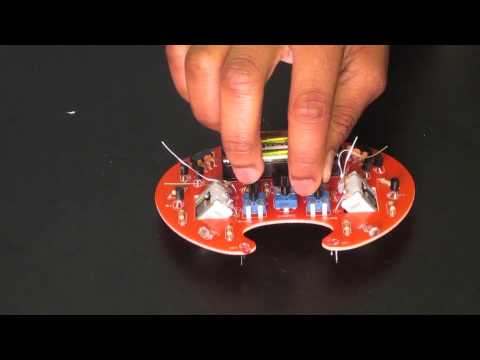
My main project is a Line following robot. The robot is in the shape of a spider, complete with a head, and legs both controlled by a motor of their own. For this project I had to clip the correct wires, make certain wires longer, (with the use of soldering, heat shrink, and a heat gun) and screw wires in correct terminals of the EMG Robotics MSP430 launchpad.
INSERT PHOTOS HERE:  ,
, 
However somewhere in between the MSP430 stopped, and I had to replace the battery pack which held the 3 volts my Spider needed.
INSERT PICTURE HERE: BATTERY PACK, MSP430.
I used these instructions to autonomous robot: http://api.ning.com/files/5Y-VDX4IZn5JLiAhOWyWNBFQTqt-1Q6jYnCnl9obJ-JAcJBw11XMV-AQBTJL0Oq27-92qYLVOnywMRcwM9lD1TVeDe3qvgRj/TheEMGRoboticsHexbugSpiderNoSolderHackingKit.pdf
In the beginning I used the following bill of materials, which like many project’s changed over time.
BSE BOM Template starter and main1 p (1)
Main project- changes and circuits
Due to unfortunate events my main project turned a whole different direction. I made the decision to transform it into a light seeking spider, similar to my starter project. Doing this, I knew wouldn’t be easy but with the help of my instructors and skill, I took the risk. Building the circuit diagram was immense by itself and included figuring out how each of the components work alone and together with each other was a great learning experience. Examples of such components include: transistors, resistors, voltage dividers, batteries, jumper wire, LDRs, etc
My updated BOM (bill of materials)
Here is my schematic for my spider:
INSERT SCHEMATIC PICTURES HERE.
Read on to follow me on my journey through milestones, and successes.
Main project blog post part 1:
I can now officially call myself a mini circuit engineer. Designing, building, and editing a circuit isn’t as easy as I’d thought it would be. Mechanical engineering the spider on its own is such a challenge and also a great learning experience. Below is the video for part 1 of completing my main project. In my previous videos I described, explained, and demonstrated the electrical components of my circuit for half my spider. In this video I now demonstrate the Spider’s legs moving once substituted for the LED. The main problem I’ve had since my last update is that there wasn’t enough current going through, the LED, therefore the motor for the legs refused to run. To fix this problem I’ve added a current amplifier from my starter project circuit. Now my circuit is up and running. My next Mission? Build the head circuit!
Milestone#3: Prototype Finished
It’s July 25, 2013. So far I’ve learned a vast amount on transistors, LDRs, voltage dividers, potentiometers, basically everything about the new circuit I’m building for my light seeking spider. Relatively speaking as said before, this new circuit will be much like the old circuit of my starter project. On my last post I talked about how I would build this circuit, and now that I’ve completed the prototype of my new circuit I’ll be explaining in the video below how it works.
Transistors are semiconductor electrical components used to amplify and switch electrical signals using three conductive pins located on the bottom of the component. These three pins each have different responsibilities. The emitter emits the current the collector picks up, and the base is sort of like a gate through which the current passes through. This brings us to the topic of using a transistor as a switch. The transistor is in saturation mode when the current flows from the emitter to the collector with no disruptions, aka with no resistance. By using the voltmeter you can measure the voltage drop between the pins of the transistor. If the voltage drop between the emitter and collector or emitter and base is zero then the current appears to be limited and the transistor is not in saturation mode. If the transistor is in saturation mode then the switch is on. The transistor can also be used as an amplifier, meaning that it can use a small current source to control a much larger one.
A voltage divider is basically two resistors that break up voltage into parts of a circuit. In my last blog post we discussed in more detail what a voltage divider is, how it works, and why it’s needed. For this new circuit I used the concepts I learned with the voltage divider circuit to understand how an LDR works and how I can use it for my new idea. Light dependent resistors (LDRs) are basically high resistance resistors that change their resistance values to correspond with changes in their environment’s light. When not enough light is shone upon the LDR its resistance level remains high, blocking current from flowing through, and thereby restricting the spider’s motors from turning on. In this case I needed two circuits, both working opposite from one another. Why do I need two circuits working opposite from one another? Well when you look at the concept of my robot’s movement you can understand why. One circuit will control motor#1- the spider’s head, while the other will control motor #2- the spider’s legs. The head moves in search of light, and the legs move once the light source is found.
Milestone #2: Revisions to My Spider
It’s July 18, 2013, and I have changed my project. Well not exactly changed it completely, I just modified it. This is due to the fact that my msp430 chip for my spider stopped working, and unfortunately for the evil forces in science quitting has never been a habit of mine. Therefore I decided to change it to a light seeking robot. This modification will make my spider an autonomous robot like my starter project. However, while my starter project light seeking robot wiggles towards the light (due to the fact that it has alternating motors) my spider version will walk like a spider towards the light. Here is a breakdown of how the spider will work. The spider, like my starter project, contains two motors, one for the head and the second for the legs of the spider. When the spider feels that light is not present in its environment it will rotate its head in search of a light source. Once this light source is found the legs will begin to move towards the source. How will the spider robot even know there’s a light source? Well similar to my starter project this autonomous robot will also have LDR light sensors. This is a milestone blog post defining how much progress I’ve made towards my goal. In order to begin building my circuit I had to first understand what a breadboard is, what a transistor is, how they work, and how to build a circuit using these components and others. First off I created a simple circuit using a breadboard, one resistor, an LED, and jumper wire. Simple enough, right? Well it was time to complicate things. I turned my attention to building this circuit:

as displayed in the schematic composed by: http://www.dummies.com/how-to/content/electronics-components-use-a-transistor-as-a-switc.html
The power voltage is 6 volts, which is connected to the switch from the left side, which is connected to one side of the 1k resistor. As we go further right, we find the other end of the resistor is connected to the base of the transistor. I actually learned the parts of a transistor and what its function is. The transistor is used to control a large amount of current with a small one. There’s an emitter, a collector, and a base. The emitter is connected to the battery, and the collector is connected to the LED. The LED is now connected to r1 which has 330 ohms, which is connected back to the power voltage source. The LED lights up!
Milestone- Hexbug Spider Robot
Programming a spider robot to follow a black line is not an easy everyday task. Actually programming anything including electrical engineering, robotics, etcetera is not an easy task whatsoever. It’s my third week here at bluestamp engineering and I’ve already made tons of progress. I completed a lot of work last week such as finishing my starter project to steps away from finishing my main project. However this week I made little progress instead backtracking. It’s the little things that matter. Little problems turn out to have a huge effect on the overall success of a project or idea. Dropping components (solder, batteries, screws, etcetera), holding parts by their wire components, and cutting wires too short (not leaving enough excess therefore limiting flexibility of wires) are habits I have that cause problems in the success of my robot, nevertheless having problems increases knowledge. I learned how to solder wires to a battery holder, while along the way learning its components. I also learned how the msp430 works and how to use the helping hands more effectively making the work easier and the impossible seem well less impossible. The helping hands make it possible for you to do more than one thing at the same time. The MSP430 is the robots new brain and eyes. Think of this change as a person getting a brain transplant. You take out the original brain which is defective for the person’s needs, and replace it with a new brain. When I found the spider’s legs moving I noticed it walked differently than it originally did. It walked at a slower pace and was turning more often as if it were looking for something. This something is the black line. You have to input a black line code into the MSP430. Once the spider locates a black line it begins to follow it. Cool huh? Despite all these problems I can honestly say I have improved a great amount. Having a pessimistic mind won’t get a person anywhere. Although having an optimistic mind about things no matter the obstacles guarantees success which is what I plan to do in order to get my bug crawling.
Bluestamp Engineering Starter Project!
On June 24 2013 I began building the mk129 bug. There were many problems and difficulties I experienced along the way, for example placing the parts backwards, using too much solder causing a blockage of current flow in the circuit, mixing up transistor parts unknowingly, and as a result having a circuit shortage. The mk129 is a robotic bug that senses and follows light. The kit is created by Velleman, complete with electrical parts. The board is not good because the circuits break easily; however it is still durable enough to maintain the circuits. The mk129 kit includes the following parts: four different types of resistors, LDRS, two switches, three HOR trimmers, transistors, two capacitors, a battery holder, LEDs, a wheel, two motors, and two AAA batteries. The resistors resist current, making it possible for just the right amount of current to pass through the circuit. The HOR Trimmers control the robot’s ability to sense light and the speed of the motor. Each HOR trimmer has a specific function. This brings us to the LDRs, which control how the robot senses the light from different angles. In my opinion the switches are one of the most important parts of the circuit. Think of the switches as a gate, current can’t flow through the circuit if the gate is open. With no voltage there is no current. In other words, without motivation, there are no results. However when the gate is closed (switch is turned on) voltage can pass through the circuit, producing current and allowing the robot to become active. In this case the voltage sources are the three AAA batteries. Connection in all circuits is a significant part of building a project. How easily the connection was disabled on my project board is one of the major frustrations I faced. All in all it was very fun and interesting building this project.
Here is a video: