
Introduction
Hi. My name is Shawheen. I’m a rising junior at Energy Institute High School, and I am participating in the BlueStamp Engineering 6-week summer program. Throughout this program, I will be programming a watch for my starter project, and I will be working on creating a mini-segway that can be controlled by a PlayStation 3 controller via Bluetooth. I chose to do this project because it can introduce me to various parts of technology that I want to learn about. I will have to work with electronics, firmware, and software in order to create the final product.

Final Milestone – Self-Balancing Robot
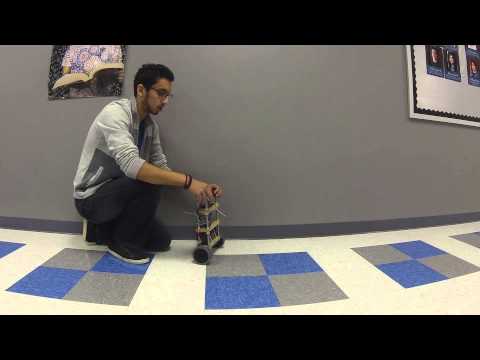
It’s been a very fun and interesting 6 weeks at BlueStamp. It’s the end of the program, and I’ve reached the final milestone in my project. Since the last milestone, I have slightly improved the robot’s balancing ability by tuning the PID values. Unfortunately, I was not able to get a second PID loop working, so the robot still tends to drift at times. I have also added connection with the PS3 remote control. Currently, I can make the robot move forward and backward by slightly changing the offset for balancing, but if I hold it for too long, the robot may fall over. To fix this, I may need to implement a third PID loop, similar to another BlueStamp student, Claire, whose code I have based my code off of. Although the program is done, I do plan on improving my robot. My next goals for working at home would be to get the robot to be able to fully balance and to also be able to be controlled with the PS3 remote with no problems.
Throughout my time here at BlueStamp, I have learned many new things. Before I started, I had very little knowledge about working with Arduino and programming in robotics, but I now feel that I have made great progress in learning about those things. I feel more comfortable working around electronics and robotics now. In addition to continuing to work on my robot, I plan on starting new projects that have been inspired by what I’ve learned through the BlueStamp with Arduino and various other robotics projects.
Final Documentation
Bill of Materials – This is the list of materials that I used to build my project.
Electrical Schematic – This document shows how all the different components of my robot are wired.
CAD Drawing – This is a 3D drawing of the Self-Balancing Robot created by TKJ Electronics. In my project, I used VEX Pro wheels instead of the green wheels in the drawing.
Journal – This is my journal where I documented what I did everyday. It shows all the difficulties I ran into and all the successes I had.
Credit – The original design of my project was based off of the robot made by TKJ Electronics. Also, my code is based on the code written by 2014 BlueStamp student Claire H.
Second Milestone – Self-Balancing Robot
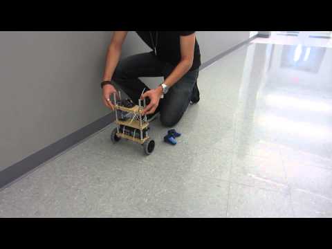
A lot has been going on since the last milestone video I’ve made. I’ve run into many setbacks that I had not foreseen, but step by step, I’ve made some good progress. First of all, the most visible change is the mounting of all the parts onto the frame that I created using MDF wood and threaded iron rods. The frame is fairly heavy, so I place the 12V lead-acid battery on the bottom level in order for the robot to keep a low center of balance.
As for the coding, which was the biggest part of the project, my original plan was to use the Adafruit IMU I have been using so far and adjust the code from a previous BlueStamp student, Claire H, and the original creator of the project, TKJ Electronics, to work with my robot. I spent a good portion of a week trying to get the code running, but I didn’t know what numbers my IMU should have been outputting in order for it to work. I spoke with my instructor and decided to get the SparkFun IMU that the previous student was using so that the code would run better. Once I got the new IMU, the robot would still not balance and the motors would jitter violently. I contacted the student who previously created the project, and got some advice on getting it to work. After some tuning of the PID values in the three loops of the code, I still couldn’t get the robot to run correctly, so with the help of one of our instructors, Andrew, I began to write a new code from scratch. This is the code running on the robot in the video above. It has one PID loop with a complementary filter running on it to try to balance itself, and it works fairly well although it tends to drift in one direction sometimes. I believe the reason for this is that although the PID loop I have tries to balance the robot, I need another PID loop that takes outputs from the motor encoders to tell the robot that it is drifting so that it can correct itself, so for the next step in my project, I want to add that extra PID loop and also get the PS3 remote to control some of the robots movements.
First Milestone – Self-Balancing Robot
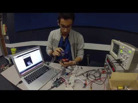
It has been about a week and a half since I began working on my main project for the 6-week program. My goals for this milestone originally was to get the motors and the IMU (inertial measurement unit) to work individually with the Arduino Due. When I was trying to get the motors to work, the dual motor driver and the Arduino Due stopped working. This was a minor setback though. We ordered the replacements, and I temporarily began to use an Arduino Uno for getting the IMU to work. I found a Processing program that shows the outputs of my IMU in the form of a 3D rabbit that rotates and moves as the IMU moves. Once my motor driver came in, I ran a simple code that drives both of the motors at 50%, and I experimented with different values and different directions as well.
Once I got my motor driver, I had already been working on getting the PS3 remote to connect to the dongle on the USB Host Shield and getting it to communicate with the Arduino Uno. After some testing with both the Arduino Due and the Uno, I found out that the SparkFun USB Host Shield I was using would not work with my Due but would sometimes work with the Uno. After learning this,, we ordered a different USB Host Shield that should work with the Due, I began to primarily use the Uno for testing the connection. As I got it to work soon after, I decided to add it to my first milestone.
Although I ran into a few different setbacks, this part of the project was very helpful to me because it introduced me to the programming that I would need for finishing the project. For my next goal, I hope to mount everything onto its frame and to get the robot balancing.
Starter Project – Big Time Watch
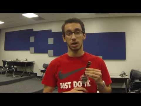
For my starter project, I decided to work on the Big Time Watch Kit. Pushing the button on the clock once displays the time, and pressing and holding the button changes the time. One of the main points of doing the starter project was to introduce us to soldering although I was already familiar with the process. I soldered many of the pieces together, such as the ATMega328 processor, the 4 digit 7-segment LED display, the 32kHz Crystal, and some capacitors. After soldering all the main components onto the board, I placed the board in an acrylic case and put on the strap. The watch functions in a simple way. The pre-programmed ATMega328 processor tells the watch how to show the time on the LED display. The 32kHz Crystal is used to manage the frequency in order to get a more accurate time, and the resistor helps manage the power that comes from the coin-cell battery in the system.
When I was building the watch, I ran into a small problem when the display was not displaying some of the numbers correctly. Some of the segments on the LED display weren’t working correctly, so I decided to look up the diagrams of the watch. I saw which connectors it was connected to on the back, so when I went to look at the connection, I saw that it wasn’t fully soldered onto the board. Once I fixed that and re-soldered the pins, the watched worked perfectly.