DIY Fitbit

Fitbits are extremely useful wearable devices that can be used to monitor steps and calories burned. This DIY Fitbit utilizes Arduino and reports data in an iPhone mobile app to be viewed.

Engineer

Shashwat M.

Areas of Interest

Engineering, Biotech, Finance

School

American High School

Grade

Incoming Senior

Final Project

For my final milestone, I got new sewable parts such as the Flora BLE Module and the LSM303 Accelerometer for my project because I needed to sew on the pieces to a wearable wristband. In addition, I was finally able to add in my battery to the Fitbit as well so now the device works without power from the computer. In order to achieve my final milestone, I first had to code my new accelerometer to be able to record raw XYZ acceleration data and convert it to total acceleration data. From there, I checked to see the variation in the acceleration, and I created a step counter to display that information. After coding the accelerometer, I had to code for the BLE module, and it sent the data from the accelerometer to the Adafruit Bluefruit app and displayed it for the user. I had wired up my parts with jumper wires to test the code so when the code successfully worked, I began using conductive thread to carefully create the connections and firmly keep the components on the wristband. The last step was when I added in a place to connect my battery so that the device could work without power from the computer. One major issue that I faced in achieving this milestone was that I had to learn how to code for the new modules, and I found it very difficult because I had to install new libraries and understand the difference between BLE and regular Bluetooth, but I was able to figure it out in the end. Another major issue that I faced was with using the conductive thread to create the connections on the wristband. It was extremely difficult to sew the thread because none of the connections could touch each other otherwise they would create a short circuit. Because of this, I even had to resew onto a completely new band because the initial connections were too close. To solve this issue, I spaced out the conductive thread, and I used fabric glue to coat the thread to prevent it from accidentally touching. Overall, this project was extremely interesting and fun, and for potential modifications, I am considering adding in an LCD display to show step count on the band itself, and I also want to add in a heart rate sensor to be able to detect stress levels for the user.

Second Milestone

For my second milestone, I eliminated all of the jumper wires that were previously present in my first milestone in order to strengthen the connections between all of the different parts and to compress the overall size of the project itself. To achieve my second milestone, I first had to desolder certain headers attached to the Arduino and resolder them so they would fit correctly on the PCB board. Next, I stripped a number of small solid wires to connect the different parts underneath the PCB board. I soldered the small wires to the appropriate connections, which created extremely strong connections as compared to the jumper wires. Lastly, I added in a header to plug in the battery to power the Fitbit without relying on the FTDI converter for power.  In reaching this milestone, I faced a number of issues. First of all, I had an issue in using the battery to power the Fitbit, and I realized that the header connecting the wires of the battery was not working correctly, so we had to order another header to attach to the battery, and for my final project, I will get the battery to work correctly. Another major issue that I faced was that in the process of desoldering and resoldering, I ended up burning the HC05 Bluetooth module, and it still connected to the Android phone, but it stopped transmitting the accelerometer data. To test if this was a problem with my module, I tested a basic transmission program with an HC06 Bluetooth module, and that module worked. I added in the new module to my Fitbit, and it worked perfectly with the app. For my final project, I will use an even smaller microcontroller and PCB board to further compress the overall size of the Fitbit, and I want to sew the Fitbit pieces onto a wristband to create a fully functioning and wearable Fitbit.

First Milestone

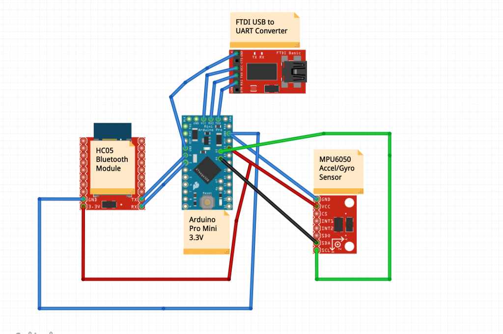
For my first milestone, I wanted to use jumper wires to connect all of the different parts and essentially get the main functions of the Fitbit to work properly. The different parts that I used to complete my first milestone are the Arduino Pro Mini 3.3v, an accel/gyro sensor, an HC05 Bluetooth module, and an FTDI USB to UART converter. In addition, I used the Arduino IDE on my computer to upload my code to the Arduino Board, and an Android device to run the Fitbit App. First, I soldered headers onto my Arduino board to make it easier to connect all the wires. Then, using the schematic on my instructions, I connected all the pieces accordingly. After everything was connected, I uploaded the source code for the Fitbit to the Arduino board. Essentially, the code tells the accel/gyro sensor to record the x,y, and z positions of the Arduino and store them, and it tells the HC05 Bluetooth module to send the data to the Android device where it is represented through graphs and calories in the app. One issue that I had in achieving my first milestone was getting the Bluetooth connection to be stable while moving the Arduino. Since the jumper wire connection of the VCC port on the Arduino and the Bluetooth module was not strong, the Bluetooth would end up disconnecting frequently when I was testing. To solve this issue, for my second milestone, I will solder all of the pieces onto a smaller board, which allows for stronger connections and eliminates the need for wires.
Circuit Schematic
screen-shot-2019-06-19-at-9.43.44-am

Starter Project: Simon Says Game With Arduino

For my starter project, I decided to do the Simon Says Game with Arduino in order to understand how to solder and become familiar with Arduino to prepare for my main project. In order to construct the game, I had to solder parts such as a microcontroller, a buzzer, 4 LEDs, and 2 on/off switches to the Simon PCB board. Essentially, the microcontroller carries the code which begins the start sequence for the game, starts the game itself with the sound, and checks to see if the user can match the pattern of the LEDs. If the user gets the pattern incorrect, the game plays the losing sequence, and it resets to the beginning again. The buzzer makes the noise for the game, and the capacitors help control the flow of electricity, and the resistor tells the microcontroller not to reset once the power is turned on. In the construction of this game, I faced one issue which was that the Blue LED was not lighting up at all. At first, I thought that I switched the polarity of the LED, but after testing, I found out that it was just a blown LED. I desoldered the LED and added a new LED. After that, the game worked very well, and I think that this starter project was extremely helpful in helping me learn how to solder.

STEM Summer Camps Coding & Robotics Classes For Kids San Francisco Coding & Robotics Classes For Kids New York Coding & Robotics Classes For Kids Denver Coding & Robotics Classes For Kids Palo Alto STEM Summer Camps For Kids in New York STEM Summer Camps For Kids in Palo Alto STEM Summer Camps For Kids San Francisco STEM Classes For Kids in New York STEM Classes For Kids in Palo Alto STEM Classes For Kids in San Francisco Code Classes For Kids Code Classes For Kids in New York Code Classes For Kids in Palo Alto Code Classes For Kids in San Francisco STEM Summer Camps For Kids

Leave a Comment

Start typing and press Enter to search

Bluestamp Engineering