Sebastian C.
My name is Sebastian Cabrejos, and I was a rising senior at Manhattan Hunter Science High School when I completed this project. My intensive project is an RC car with claw controlled by one’s hand gestures based on this instructable. I felt that this particular project best suited to my interests in mechanical and biomedical engineering.
I am currently a Mechanical Engineering sophomore at Johns Hopkins University.
Engineer
Sebastian Cabrejos
Area of Interest
Mechanical Engineering/ Tech Startups
School
Johns Hopkins University – Class of 2022
Year
Sophomore
Final Project
Schematics
Bill of Materials
Arduino Code
Reflection
In 6 weeks, I discovered both a purpose and interest in coding. I saw firsthand how coding and building are equally exciting and challenging. I learned how collaborating with my peers and instructors made the process of creating my projects smoother but not any less intimidating. Thanks to BlueStamp I not only have a gesture-controlled car with a claw but an understanding of what I wish to pursue as a career.
My final milestone is connecting the flex sensors to the car and claw via the Xbees. I had to write a page of code for each the sender and the receiver having no knowledge of Arduino code prior to this program; however, my knowledge of some HTML, CSS, Python, and C++ made the process easier. The sender contains the XBee.write() function to send commands to the receiver and sends certain commands based on how much the flex sensors are bent and if an LED is on or off. The receiver contains the XBee.read() function, which takes in certain commands to power either the motors or the servos. I struggled with the code more than anything because it needed to be debugged several times in order to work properly. I enjoyed watching as the flex sensors with each unique gesture move the car in various directions and swivel the claw around.
Second Milestone
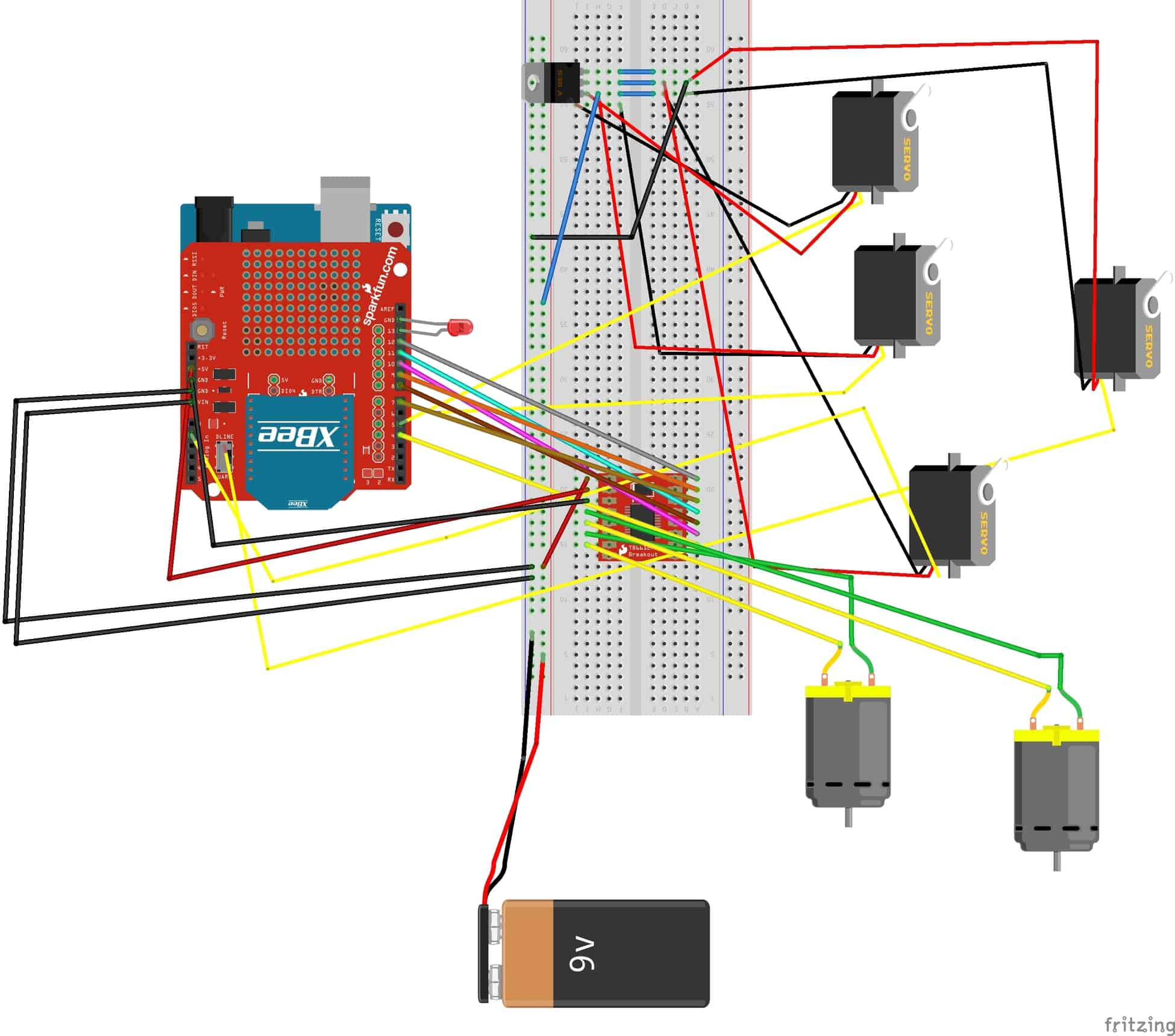
My second milestone is completing the chassis and moving the claw and motors though not yet by the use of my flex sensors. This was probably the most physically intensive part of the project. I had to use an electric drill to create the holes for all the screws and hand-screw in all the tiny screws into place. The code for claw is a simple test that moves all of the four servos at 90 or 180 degrees. The circuitry was equally as complicated because of the h-bridge, which is this small board needed to power the motors, had many unique ports necessary to power everything. The servos and motors had a simple piece of code yet required such intricate wiring connections. I struggled with the circuitry the most since I was often unsure if the issue was in the code or with the wiring. I enjoyed building each piece of the claw and finally seeing it turn into the same claw as seen in the instructions.
First Milestone
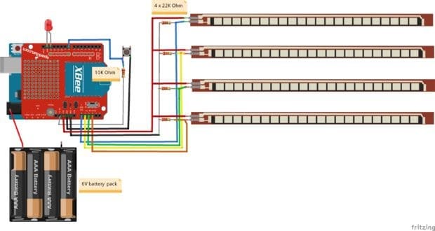
My first milestone was successfully attaching all the wires from the flex sensors to the Arduino and getting results from moving each sensor. I plugged each sensor to my breadboard to connect all of them to 5V and Ground and to the Analog 0 to 3 on the Arduino. I’m currently at the phase where I could see the resistance of each flex sensor but not control the motors nor the servos. I’ll show you the code for testing out each sensor, which test every analog port in a loop for both resistance and bend. As you can see, all the flex sensors are properly functioning, but I have yet to connect my second Arduino to this Arduino using my Xbees and get the flex sensors to control the motors and servos. I struggled with tweaking the code so that I could read the resistance for all the flex sensors rather than just one. I enjoyed seeing the flex sensors actually showing results each time they were bent.
Starter Project
My Starter Project is the Mini-POV3. It has 7 key components: microcontroller, 20-pin socket, resistors, diodes, red LEDs, serial port, and a circuit board. The microcontroller or the chip is what controls the way the lights work to create an image. To program the microcontroller, you must connect a USB-Serial connector to a computer and the female connector and alter the software from there. The 20-pin socket holds the chip in place and makes it so that the chip could be replaced if necessary. The resistors control the flow of current, so the current doesn’t overflow into the LEDs; the diodes direct the current only towards the red LEDs. The circuit board is used to connect all the components in one place and allow the current to flow from the batteries. I enjoyed soldering the pieces onto the board and seeing all the red LEDs blink as I turned it on. I struggled with figuring how to update the software and reading all the instructions in one sitting; it took a few tries to understand that the binary where an 01010101 makes odd lights turn on; in other words, each 0 or 1 refers to each of the eight red LEDs.
Comments
nice work