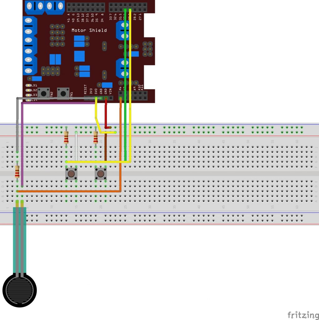
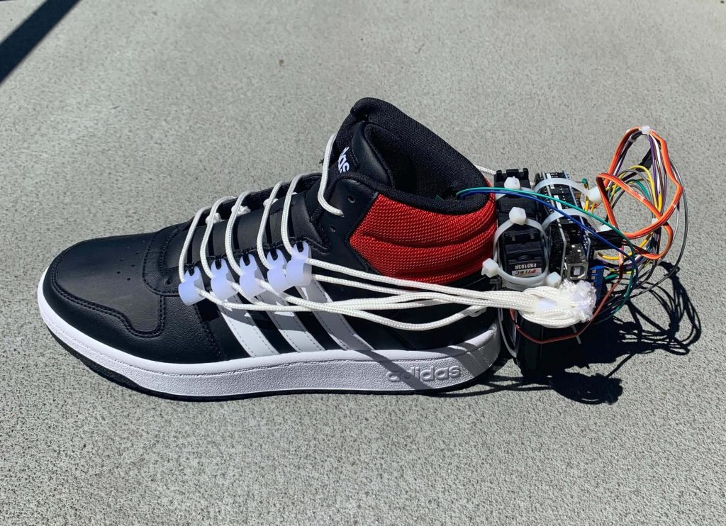
Self Lacing Shoe

Have you ever asked for a less physically demanding solution when it comes to tying your shoes? Well I have, and it wasn’t Velcro!

Engineer

Sebastian B.

Area of Interest

Mechanical Engineering

School

Gunn High School

Grade

Incoming Junior
img_8071-1-1-1

Reflection

During my time here at bluestamp I definitely learned a ton about coding, soldering, dremeling, and other cool skills that I can apply later on to other cool projects. But I think I learned something much more valuable than that as well. I learned a lot more about what it means to be an engineer! There is a lot more to it than what people see on the surface. For instance, I had no idea how important documentation was coming into this camp. Documentation is a major part of the process. It allows you to show off your work and keep track of it in detail as you continue to work. Another thing we learned here is the importance of public speaking. Being able to communicate your ideas and creations to other people is an incredibly important skill that can distinguish the good from the great. Bluestamp emphasized this by having guest speakers come in every day at lunch time to speak about their field of study. Not only is it a super useful skill for an engineer to have, it can be applied to anything you do for the rest of your life. I’m going to miss coming in every day to work on my shoe, being surrounded by supportive and flat out amazing instructors and students alike. This camp has given me better experiences and learning opportunities than I could have ever imagined, and it will always hold a special place in my heart. 

Final Milestone

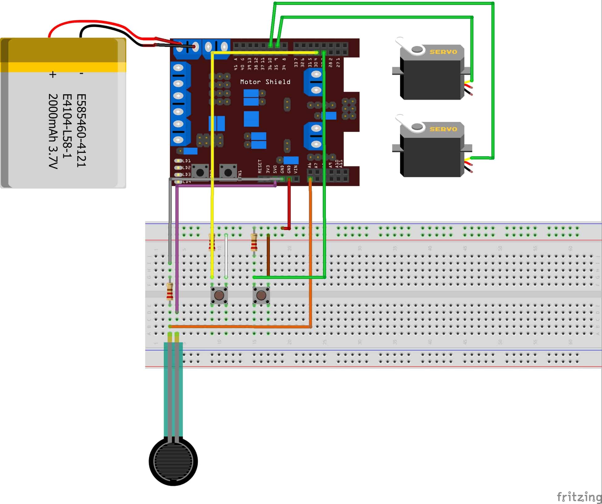
Final Schematic
sebastian-final-fritzing-diagram_bb
My final milestone for my self lacing shoe was essentially the completion of the project, not including modifications. The first thing I worked on after my second milestone was moving all of the wiring from the  breadboard to the perforated board. This took a couple of days as I really wanted to make sure I did everything correctly because there is not much room for error. I learned things about the perf board as I went along. For instance, it does not have power and ground rails like a breadboard does. If you want something to share a same power or ground you need to connect it via a separate wire or a solder bridge. Having to add extra wires complicated my process slightly because they went on the back of the perf board, which ideally would have been flat for an easier mounting process. Having a couple wires sticking out of the back forced me to use zip ties instead of velcro. After I attached the finished perf board onto the back of my shoe, I worked on attaching the laces to the servo arms. I wanted to use plastic loops to screw into the servo arms and attach the laces, but for the right side where there is only one lace, the plastic loop was too large. Instead, I made my own plastic loop by drilling into a zip tie. This made the single lace fit more snug so it would not slip out. For the other side where I have 5 laces, the plastic loops worked just fine. I secured them to the servo arm with a little screw, and they were ready to go. As of right now the best way for the laces to tighten is for the servos to only spin 180 degrees, because the laces do not spool in on themselves, so any more than 180 would not do anything. Because of this, I had to figure out the optimal length for the laces to have the most visually pleasing tightening motion while limited to a range of motion of only 180. The last thing I did was replace my force sensor, because for some reason my old one stopped working, which had me worried that the error was something else that would have been more difficult to fix. Identifying that it was the force sensor by using a multi-meter was a relief because it meant I did not need to take everything apart again. A modification I hope to make in the near future is some sort of spooling mechanism to be able to achieve more tightening motion. 

Second Milestone

Second Milestone Video

My second milestone was to finalize my code, not including modifications, and to get the servos, motor shield, and battery pack mounted on the back of the shoe. To mount these components I had to make a metal mounting plate that I cut out using tin snips, and screwed into the back of the shoe. Once I made sure the mounting plate was secure, I was able to start mounting the other things with zip ties and Velcro. I used zip ties for the battery pack and servos, and I used Velcro to secure the motor shield on the back of the motor shield/arduino. After having completed this, I began working on the code. My first idea was to use some kind of timing function to have the servos stop spinning at a specific point (when the laces are tightened). This ended up not working. I considered using other functions too such as a delay, a millis, and even just a string of if else statements. I realized that these would not have worked very well with any modifications I wanted to add later on, as well as even just by themselves. I then decided to incorporate 2 buttons to be able to physically control when the laces will loosen and tighten. I wanted the buttons to only be functional if the force sensor has a reading of at least 100 though. I had to learn about buttons and how to incorporate them into my code. This took some time, and was quite a confusing and frustrating process. After speaking with my lead instructor, Asher, I was introduced to a new idea. He explained the concept of a state machine to me, which is what I ended up using. A state machine is essentially a series of states, that can be traveled through by way of inputs, and the moving parts of each state being the outputs. The way it works is the force sensor waits for a reading above 100 to move on to state 2. In the second state it looks to make sure the force sensor is still reading a certain value, and then also looks for one of the two buttons to be pushed. Pressing the green button will send it to state 4, which will tighten the laces, and pressing the red button will send it to state 3, which loosens them. Throughout all 4 states, it is making sure the force sensor is being pressed, otherwise it will not run. After some time, one of my buttons started working with the state machine, but the other would not. It was confusing because I was sure the code was correct, so I looked into the wiring and other physical components to see what was wrong, but could not find anything. I used a multimeter and noticed the faulty button was not getting any voltage. After replacing the actual button for a better one, it still did not work. After some more careful examination of my code, I realized it was a matter of using an “if else” statement, as opposed to the “if” that I had, as well as switching around some brackets. This fixed it and got it working. Getting through this milestone was definitely the hardest part of my project as it was the most coding intensive. I had to learn a lot of little technicalities about coding along the way to be able to troubleshoot when things went wrong. Brackets play such a huge role in the formatting. A small displacement of a bracket could throw off the entire code, which I learned the hard way. Overall I am very happy with how this has turned out so far, and I am even more excited to finish the project and add cool modifications.  

First Milestone

My first milestone for the self lacing shoes was to get the force sensor working with servo, and to get my custom laces fitted. For the laces, I took out the original thin black ones and exchanged them for some thicker nylon cord, and attached some plastic loops by way of zipties for the new laces to feed through as they were too big for the pre existing holes. The laces had to be laced in a special way for them to be able to be pulled easily with more slack, giving them that better visual of self tightening. The thicker cord also gives an all around better/cleaner appearance. At first getting the thicker cord through the small holes was challenging, but after making the holes bigger by pushing an allen wrench through them and duct taping the tips of the cord to feed them through more easily, I got it. As for the sensor and servo, it was very challenging at first because I had no prior experience in coding, so I had to learn as I went along. It would get very frustrating at times, but seeing the minor successes along the way motivated me to keep learning and moving on. The first small goal I set for myself was to get the servo moving at all. After succeeding at that, I played around with the code a little and figured out how to control the servo a little more and make it run when and in what direction I wanted. I then set the servo aside and tried to figure out the force sensor. I first tried to get the force sensor to read any value at all through the serial monitor. Once I had that, I tried to connect the two, and have the servo respond to the force sensor. This was the most difficult and frustrating task. When I first got the servo reading the force sensor it would spin completely randomly. I tried controlling it by using a map function that basically allows the servo to run only within a certain parameter of values. This did not work, and made the servo respond very strangely. I then opted for an IF/ELSE statement. The IF statement I used gave the force sensor and servo a specific condition, saying it will only allow the servo to run, if the sensor reads a value of at least 100. This worked wonderfully, and was very exciting to see the servo spin when force is applied to the sensor. The main thing I learned throughout the process of this first milestone was to take things in smaller steps and to focus on the smaller victories as opposed to being overwhelmed by the entire project as a whole. Seeing a little progress being made after every obstacle is the sole reason for my persistence. Overall I am very happy with what I have achieved so far, and I am excited to keep working on the rest of the project.

Starter Project – MintyBoost Phone Charger

For my starter project I built the MintyBoost kit. The MintyBoost is a little phone charger that draws power from two AA batteries, and with that power charges a device. The way it works is it takes the 3 volts given by the batteries (1.5 volts from each battery) and raises them to 5 volts to be able to adequately charge a phone by using a boost converter. The boost converter itself is essentially a small computer that tells a series of capacitors, a power inductor, and a diode when, and when not to produce power. The energy from the original power source, the batteries, flows through the power inductor, and sends it on in the same direction because of the diode. The power inductor would usually want to discharge energy back in the opposite direction but what the diode does is it forces the current through a one way channel, so the discharged energy does not go back, and instead advances to the capacitors, where they are then stored in the form of an electrical field for later use. This is a cycle that repeats itself until the boost converter says to stop. All the stored energy in the capacitors is discharged at once, and with all that extra power is able to adequately charge a phone with 5 volts. It is a bit of a trade off, as it can not charge an iPhone more than roughly half way, but in exchange, outputs a good amount of power. Learning how to solder proved very useful as there was quite a bit of soldering required to complete the starter project. When it came time to troubleshoot, as something went wrong and I did not know what, learning about each electrical component and how they work was essential in identifying the issue and fixing it. After re-soldering a couple connections, I resolved the problem, which ended up being a faulty connection. Overall I am very happy with the results, and feel much more comfortable tackling the main project after being introduced to the world of electrical engineering with the starter.

STEM Summer Camps Coding & Robotics Classes For Kids San Francisco Coding & Robotics Classes For Kids New York Coding & Robotics Classes For Kids Denver Coding & Robotics Classes For Kids Palo Alto STEM Summer Camps For Kids in New York STEM Summer Camps For Kids in Palo Alto STEM Summer Camps For Kids San Francisco STEM Classes For Kids in New York STEM Classes For Kids in Palo Alto STEM Classes For Kids in San Francisco Code Classes For Kids Code Classes For Kids in New York Code Classes For Kids in Palo Alto Code Classes For Kids in San Francisco STEM Summer Camps For Kids.

Leave a Comment

Start typing and press Enter to search

Bluestamp Engineering