
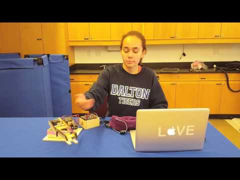
Hi, my name is Sara! I am a rising junior at The Dalton School. For my starter project, I made a “MintyBoost” portable USB charger that converts 3V to 5V. My main project is a Mind-Controlled Robot Arm, which is connected to an EEG headset that measures one’s brain waves. I chose this because I’m very interested in Neuroprosthetics, and this uses similar technology. I also wanted to learn how to use engineering to help people.
Mind-Controlled Robot Arm


I have gotten my Mind-Controlled Robot Arm to work! Since my last milestone, I wrote code that compares the values of one’s attention to their levels of meditation for each degree of freedom of the robot arm. Once one state of mind becomes stronger than the other, a specific servo will move in a certain direction. I used if statements in order to compare these values. I continued to use the Arduino Brain library, which converts the brainwaves that the EEG receives into numerical values that correlate to the strength of the brainwaves received.
In order to reach every degree of freedom of the robot arm, I added a mode switch. Each joint correlates to a different mode in which attention and meditation are compared. Every time that the button is pushed, the Arduino recognizes that the state of the button has changed, and then switches modes. Some engineers in the past have actually been able to switch modes with different eye movements by measuring the length of eye blinks, and I would love to explore this feature in the future in order to make the robot arm completely hands free.
Since this is my second year at BlueStamp, I wanted to challenge myself by making a complex project. This project proved to be very difficult at times. My greatest obstacle was trying to make sure that the signal from the EEG was strong and reliable. In order to overcome this challenge, I had to solder many of the same joints numerous times as well as relieving strain on the wires by angling them in different ways and by gluing the wires down. I also had to continue to use Mattel’s MindFlex headset because homemade electrodes are not very reliable.
This year at BlueStamp has been a great experience. I got to learn a lot about how engineering can be used to actually help people. I learned that I really enjoy Mechanical Engineering while building the robot arm. I had a lot of fun designing the robot arm and seeing it come to life. I also learned that in order to make a well balanced project that looks nice, precision can be very important. I was also tasked with learning about the business side of engineering. I was able to see how I would be able to actually market and sell my project. I had a lot of fun working on this project, and I learned a lot about engineering!

Bill of Materials
My Code
Arduino Brain Library
Second Milestone

For my second milestone, I have finished the EEG headset. Since I wanted this to be a much less invasive version of a Neuroprosthetic, I decided to put the circuitry into a hat. In the brain, neurons fire electrical pulses in order to communicate and signal to each other. Electroencephalograms (EEGs) measure this electrical activity. In order for my hat to actually pick up and analyze these brainwaves, inside the hat, there are three electrodes, a battery, a switch and an EEG chip. There are two reference electrodes that attach to one’s earlobes. These electrodes act as a baseline for the EEG chip by showing what it looks like to receive no brain signal.
There is also a main electrode placed in the center of the forehead. This picks up the brainwaves and sends them to the EEG chip to be processed. Emissions of Delta, theta and alpha waves correlate with high levels of meditation, while gamma and beta waves correlate with one’s levels of attention.
In order to get my robot arm to work, the ability to measure one’s levels of attention and meditation is very useful. I will compare the values of these two states for each degree of freedom in my robot arm. If attention is stronger, a specific servo will move in one direction, and the servo will move in the opposite direction if meditation is greater. For this milestone, I’m using an example from an Arduino library called Brain that measures the strength of each brainwave that it receives and prints the strength in the form of numbers into the serial monitor. The example I used is BrainSerialTest. I then also found an EEG graphing program that allows me to visualize the strengths of each brainwave. I faced many challenges while building this. Originally, I was going to use my own design for the electrode and my own circuitry, but that didn’t work for an unknown reason so I used Mattel’s MindFlex headset that has its own electrode, chip and a better signal. In order to hack the headset to work with my Arduino, I soldered a wire from the ground and TX pin on the Neurosky chip and connected them to the Arduino. The TX wire is plugged into the RX pin on the Arduino. For my next milestone, I might try to make my own electrodes and I will have the headset working with the robot arm.
First Milestone
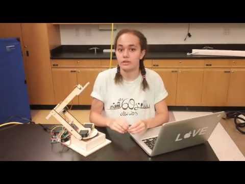
For my first milestone, I completed the robot arm. In order to create the robot arm, I first designed it in CAD using a 3D design software, Onshape. I designed the arm as a whole not to scale, and then the parts individually with the correct measurements so that they could be laser cut. In order to get the joints to move, I mounted servo motors onto the laser cut pieces of wood.
Hobby servos are better for robot arms than normal motors because they have a range of 180 degrees and can securely hold specific positions. Inside a servo, there is a potentiometer and a DC motor. The potentiometer provides constant feedback to a control circuit that tells the motor to move until it reaches a specified position. There are three wires on a servo, one to power, one to ground and one is the control wire. The angle of the servo is determined by the duration of a pulse emitted by the control wire. This is called Pulse Width Modulation (PWM). If the pulse is shorter than 1.5 milliseconds, the servo will move counterclockwise, and if it is longer, the servo will move clockwise. Servos move between 0V and 5V or 0V and -5V, depending on which direction the servo is turning.

In my design, I have two servos on the circular base to make the shoulder joint. For every other joint, I only have one servo, and this is because the shoulder carries more weight and needs to have more power to move. In my code, I wrote it so that if one types a specific number into the serial monitor, a specific servo will turn in the direction that the number corresponds with.
I faced many mechanical challenges while building this project. Originally, I had a different claw that was assembled from a kit, but it was too heavy for my arm to support. The weight caused the arm to topple over and break the supports that I had at the base. This prompted me to replace the claw with a smaller version, and add a rectangular support wall. The claw also uses a micro servo to make it even lighter.
Mechanical Drawing of Robot Arm
Starter Project
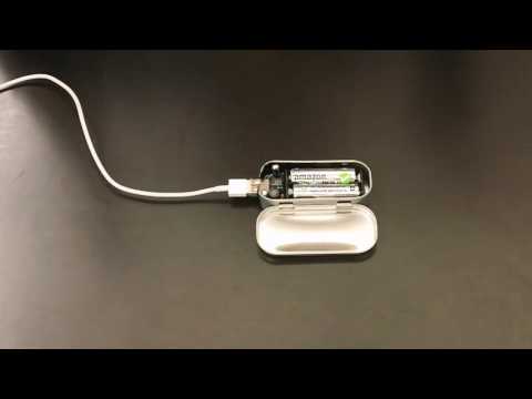
For my starter project I made a MintyBoost portable battery-powered USB charger as my starter project. The charger converts the 3V from the 2AA batteries into 5V. There are lots of different electrical parts incorporated in this project. There are capacitors which help smooth the input and output voltages as well as reduce noise. A power inductor is also included which is a coil of wire that has a magnetic field created by current and stores energy. It works with the IC boost converter chip to convert the 3V to 5V.
The chip acts as a switch and continues to switch open and closed, allowing current to flow into the power inductor. The inductor opposes change in electrical current, so in order to balance out this addition of current, it sends out electrical energy converted from magnetic energy into the capacitors.The chip tells the power inductor to keep sending energy into the capacitor until it reaches five volts.
A diode is also incorporated in order to make sure that current only flows in one direction, from the battery to the USB port. Resistors are included to limit current flow to protect the IC chip and the circuit in general.There is actually a specific kind of resistor used in this circuit that Apple products use to identify what kind of charger it is, which makes this resistor very important for iPhones to be able to recognize the MintyBoost charger.
I faced a few obstacles while building this. A wire connected to the battery holder fell out after I soldered it, and I had to desolder the hole in order to fit the wire back in. I also had to make sure that there was electrical tape underneath the board in order to prevent a short circuit.