
Hi! I’m Sara, and I’m going to be a sophomore at the Dalton School in the fall. For my starter project, I made a MintyBoost portable phone charger. I chose this because I wanted to make something that I could actually use all the time. My main project at BlueStamp was a voice activated LED display, which was really fun to make. I chose this project because I love art and painting, and I wanted to create something that combines engineering and art. Throughout this process, I gained so much valuable information and experience that I am excited to use in future engineering projects!
Voice Controlled LED Matrix


Final Milestone
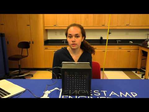
I have finally finished!! Since my last milestone, I put my project in its case and added new designs. While the new patterns may not seem very interesting, they show that I will be able to make all sorts of designs. I can now control the rows as well as the columns, so individual LED’s can turn on independently from its entire row. The anodes, which are organized in rows, are defined in an array by stating which pins the anodes are connected to the Arduino. Then, depending on the pattern, I sent strings of binary to determine which anode gets turned on or off. The strings of binary are split up into eight groups, that correspond to the pin numbers from the anode array. I also included code that would update the matrix so that one row displays whatever pattern it was given, and then turns off. This happens to all of the rows, but to the human eye it looks like all of them are on at the same time displaying the pattern the matrix was set to show. Since I can control the rows and columns, I can create many designs and patterns that are more complicated than the designs from my last milestone. It is even possible to make moving animations!
Using the voice control code from my first milestone, I made it possible so the patterns and lights will turn on when activated by voice. I learned a lot about engineering by making this project, and even though I had many problems, it was really fun to make!
Documentation
Schematic:

Bill of Materials Arduino Code : Matrix Python code
Second Milestone
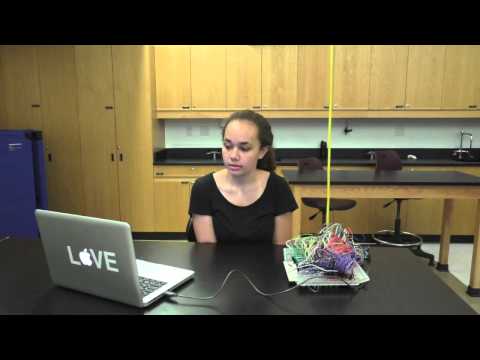


After a lot of time and effort, I completed my second Milestone. Once I had the voice control ready, I moved on to build the physical LED light display. I began by drilling 64 holes into a piece of wood where I glued in the LED’s. In order to use only three of the Arduino’s pins, I incorporated shift registers in my project. Shift registers shift out a byte of data bit by bit. Each time the clock pin (the second pin) is pulsed, a bit is passed to the register. Once all 8 bits have been transmitted, the data from each bit is read and sent to the output pins on the register. A bit can either send that it is HIGH or LOW. I connected three shift registers, one for each cathode color on an RGB LED, and each output pin was connected to eight cathodes. Each cathode is attached to a resistor that 220 ohms of resistance. This means that I only needed to use three pins on the Arduino for 192 cathodes. I connected the 64 anodes to eight transistors to be used as switches. Each group of eight is connected to a pin on the Arduino. The bits are processed in the shift registers so that all of the cathodes are ready when the anodes are turned on.
So far, I can control the colors of the LED’s by sending them strings of binary. When it reads a zero the output pin will become HIGH. This means that when turned on, all of the cathodes connected to that pin will be set to HIGH. This allows colors to be mixed by turning on different combinations of the cathodes. (Example: Red cathodes and Green cathodes turned on displays yellow) This also enables control over the colors of individual columns, so different patterns can be made.
I came across many problems before I was able to finish my second milestone. Since there were so many wires, it was easy to get confused at what I was looking at and for the wires to pop out, which led to mistakes. After rewiring my project numerous times, I decided to glue the resistors into the breadboard with hot glue to reduce the frequency of the wires popping out. Once they were glued in, it was much easier to deal with the project, and I was finally able to finish the second milestone.
First Milestone
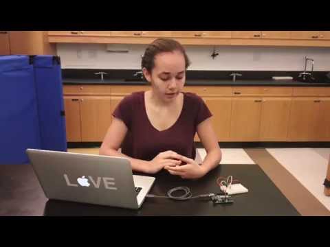
My main project for BlueStamp is a voice activated lamp that will change color or turn off when given certain commands. After a lot of work, I got the voice activation to control a Common Anode RGB LED, which was my first Milestone. It took a while to find a software that would be compatible with my computer, so I could take the project home in the future. It turned out that all I needed was to use Python and Arduino.
The first step I took was to import PySerial, which connects Python and the Arduino so they can communicate. Then, I declared the variable “connected” as “false” to act as a sign that the connection between the Arduino and Python is closed. Then, “ser”, a serial variable is initialized, which will interact with the Arduino. When initialized, a serial variable requires the port that connects the Arduino to the computer to be defined. It also needs to have the baud rate set within the serial variable, which I set to 9600. The baud rate is the rate at which information is sent and received by the serial controller (1). Next, since the connection has been made between the two programs through the serial variable, “connected” becomes true. The code then writes a number which correlates with a certain color that will be sent to the Arduino code as a string. PySerial sends the number to the Arduino’s serial monitor, where it is read by the Arduino.
The Arduino code states that if it receives any input, it will determine which number it is in order to display the correct color. The Arduino receives the number from Python, and sets whatever it reads as a variable. By doing this, the Arduino will continue to read the numbers that it receives. I bumped into a problem here because I originally did not have the variable, so the Arduino would only read the first number that the Python code sent. In the Arduino code, the numbers are given certain colors. I set all of the colors to a lower brightness than the maximum because otherwise, it would be too bright.
After I wrote both of these codes, I made applications that would run the Python code. Since the Python code activates the Arduino, I only need to open the application for the light to turn on. Once I finished the applications, I wrote commands in Mac’s Dictation ability. Each command would open a different application that would open a Python code for a certain color. The commands are: Red, Blue, Green, Yellow, Purple, Cyan, White and Off. Now I can speak any of these commands into my computer’s microphone while the Arduino is plugged in, and the LED will change color or turn off. My goal is to make the lamp be able to dim as well, and to build it to be as aesthetically pleasing as possible!
Bobbert72. “Arduino and Python.” Instructables.com. N.p., n.d. Web. July 2015.
http://www.instructables.com/id/Arduino-and-Python/?ALLSTEPS
Starter Project
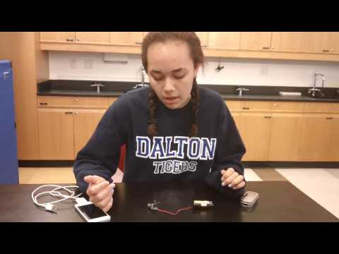
Hello! I’m Sara and I made a “MintyBoost” portable USB charger kit from Adafruit for my starter project. The charger is powered by 2 AA batteries that send about 3 volts through the circuit. The three volts are later increased to five volts through a power inductor. On the PCB (Printed Circuit Board) there are two different kinds of capacitors, and both are there to store energy from the batteries and stabilize the input and output voltages of the MintyBoost. There are resistors on the board that are there to limit the current going through the circuit in order to protect the IC chip and the whole circuit in general. Only one diode is included in this circuit, and it makes sure that the energy is only flowing in one direction to the USB port. The IC socket is included in order to allow the chip to be replaced if damaged. The chip, with the help of a power inductor, converts three to five volts. The chip tells the power inductor to keep sending energy into the capacitor until it reaches five volts.
While building this, I learned the basics of circuitry. In the end, I made a functioning charger, but I encountered many difficulties. One of the electrolytic capacitors was damaged, and I learned the importance of stabilizing the input and output voltages because it would not work after this. There must have been another problem as well because even after replacing this it would not work. With a new kit, I was able to heighten my soldering and desoldering skills. After I made the functioning circuit, I made a case for it! By cutting the front section of an aluminum box and sanding it down, I made a space to put the USB port. This was a really fun experience, and now I have a functioning charger!
Would you clarify a few tignhs? Do you want to drive all red, green and blue LEDs of 8 RGB LEDs (that will take 24 outputs, so 8 more than the 16 provided by a TLC5940). What RGB LEDs are you using? We need to know if they are common anode or common cathode (your wiring looks like common cathode, which won’t work with a TLC5940, which can only sink current. Common cathode will need a different chip). Also blue might not switch on using 3.3V, so will need 5V. Must it be through hole electronics (e.g DIP), and not surface mount. Do you care if it uses 3 chips instead of one? Nov 8 at 0:37