
Table of Contents
Biography | Final Milestone | Documentation | First Milestone | Images | Starter Project
Biography
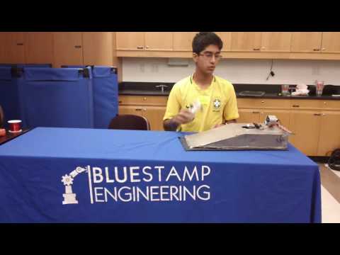
My name is Samir and I am a rising junior at Friends Academy. For my starter project, I chose to build the Bigtime Watch. I chose this project because I wanted to build something fun and useful. I also wanted to make something that would allow me to use my own experimentation to learn from it. I chose to make a hovercraft for my main project because I wanted to make something that would present challenges and obstacles that I would have to overcome. Unlike other hovercrafts, I decided to use an Arduino for the main controller of my hovercraft. This allows me to have more freedom in customizing my vehicle and allows me to write my own program.
My goal for this hovercraft is to have a working vehicle that lifts off the ground. I also would like add many extra modifications and features to it including different driving modes, a spoiler, and lights. One feature I would like to add is having the top open so that the components inside can be accessed. Another goal I have for this project is for the final design to look good, but still be streamlined and efficient. I would also like to take advantage of the opportunity to use an Arduino and write an efficient code that lets me control all the features on my hovercraft.
In the past, I have had a lot of experience with robotics and engineering. I participated in the Lego FLL robotics competition for 3 years, and was my team captain for 2 years. My team made it to Long Island finals all three times. I am currently on World Robotics Olympiad team. This is my 3rd year being in this team. During my first year, my team made placed 19th in the international championship in Russia. During my second year, we placed 8th in the US. I am also currently on my school VEX team. We made it to the quarter finals of regionals during my first year, and semifinals during my second year. Last year, I also mentored my younger brothers FLL and led them to competing in the Long Island Finals. Last summer, I taught a robotics and programming course to 8-12 year olds at Future Stars summer camp. I also participated in an engineering course at the Ross School and built a 3D printed autonomous car. Earlier this summer, I did a 2 week engineering and artificial intelligence course at Cornell. During my free time at home, I enjoy 3D printing things and making things with my Arduino.
This hovercraft was a really fun project to work on because the Arduino let me have full freedom in customizing my vehicle. The Arduino allowed me to add all the features I wanted and control them from the PS2 controller. Since I had so much freedom to expand on my hovercraft, I faced a lot of difficulties and challenges during the build and program phases of my project. For example, I had many connection problems between my PS2 controller, receiver, and Arduino. I also faced many electrical, mechanical, and programming problems when connecting my spoiler servos to my Arduino. One of the biggest obstacles I faces throughout this project was that my depron was too thin to hold the weight of my vehicle. To overcome this difficulty, I had to reinforce my whole hovercraft with 3mm depron. This presented many difficulties because the depron glue and hot glue were not sticking well to my 3mm depron. Also, it was very difficult to make a permanent frame for vehicle before I knew where components needed to be placed for balance. Another challenge I face was that my ESCs often overheated. I was not able to find a longterm solution to this problem, but I added vents from my fan to cool the components. This cooling method does not prevent the ESCs from overheating but it lets the ESCs run for a longer time before overheating. Although I faced many obstacles when building my project, I really enjoyed this build and would definitely like to continue building similar projects in the future.
I really enjoyed my experience at BlueStamp for many reasons. BlueStamp did not just teach me how to build a hovercraft, but also taught me the skills to building anything on my own. The staff taught me how to find the answers to my questions instead of simply giving them to me. They encouraged the use of the internet and other tools that would be used in the real world to help find answers. Also, after a build was completed, the instructors did not let me move on until I knew how every single component to my project worked. This helped me understand all the new things I was learning, and reinforced the things I already knew. The BlueStamp instructors also made the classroom a really fun environment, while still keeping it productive. Overall, I had a really great experience at BlueStamp Engineering.
Hovercraft Documentation

This is a CAD image of the exterior design of my hover craft: Exterior Body Model. I used Tinkercad.com to make the design.

This is a CAD image of the interior design of my hover craft: Interior Body Model. I used Tinkercad.com to make the design.

This is a schematic drawing of the electrical components of my hover craft: Schematic. I used Circuits.io to make the drawing.
I used the Arduino programing platform to code my hovercraft. Here is a link to my final code. This program includes the code for the modifications: spoiler, EL wire, and multiple driving modes.
Images

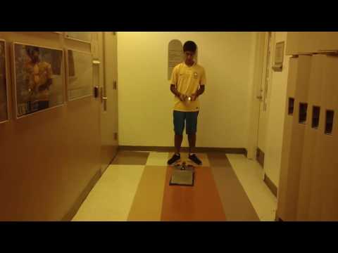
This is the final exterior picture of my project.

This is the final interior picture of my project.
Final Milestone
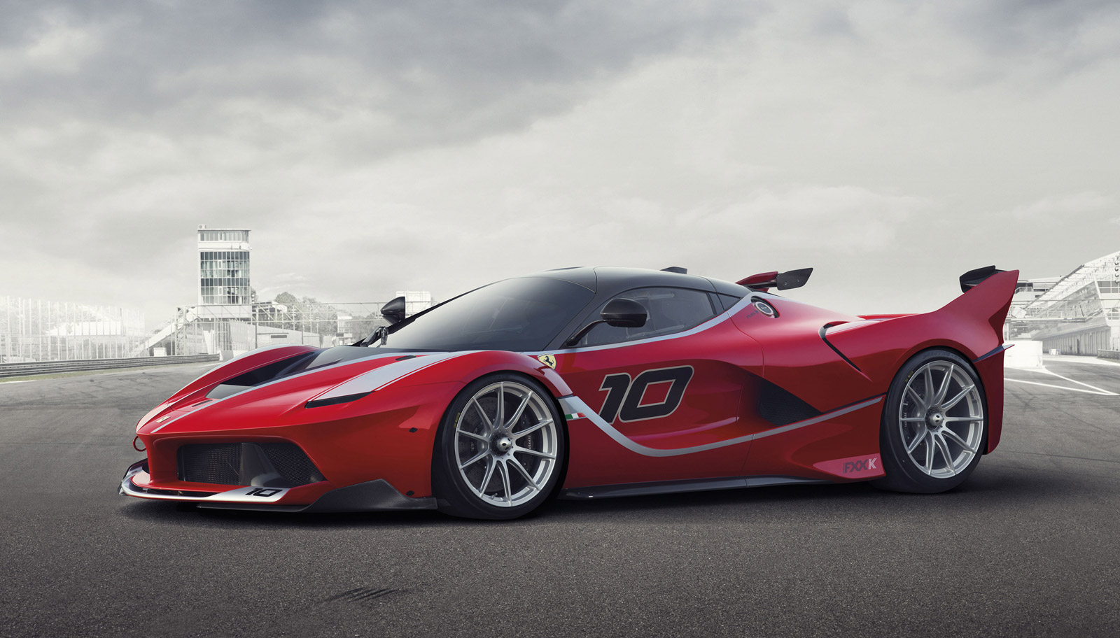
For my final milestone I successfully attached a spoiler to my hovercraft. I wanted to build a spoiler for my hovercraft because it would look good, I wanted to use more features of the Arduino, and I wanted to add some features from real sports cars. My spoiler stays folded down unless the hovercraft is in sport plus mode or race mode, similar to the spoilers on the Porsche 911 Turbo S and the Ferrari LaFerrari. I used a servo to attach the spoiler. Attaching this modification presented many challenges because the Arduino did not have enough voltage to control 2 more servos. My original idea was to have 2 small spoilers, one on each side like the Ferrari LaFerrari FXX K. However, to do this, I would need to use 2 servos, 1 for each spoiler. To avoid this problem, I decided to make one spoiler and control it using only 1 servo. After attaching the servo, building the spoiler, and programming it, I came across another major problem. The new program had a major glitch that did not allow the controller to connect to the Arduino. Instead, it just turned on all the motors and did not allow them to stop. It also did not allow me to control the servos. I spent several hours checking and recoding each individual component of the hovercraft. After confirming that each component worked, I was still experiencing the same glitch. I continued experimenting with the program until I found a solution. After a very simple fix to the program, the hovercraft was working with the spoilers attached. Another thing that I modified on my hovercraft is the EL wire. Instead of powering the wire through 2 AA batteries, I decided to rewire them and connect them to my Arduino. I also added new EL wire to the spoiler and connected it to the Arduino. Attaching the EL wire to the Arduino allowed me to control the wire from the PS2 controller. I also attached a voltage current sensor to the battery. This sensor will automatically start beeping when the battery reaches a low voltage.
First Milestone
For my first milestone I completed the mechanical build, electrical build, and programming for my hovercraft. The chassis for my project consists of 2 main pieces: the top and the bottom. Each of these pieces are made from 3mm depron and are 10 inches by 20 inches. These pieces are connected using velcro and 3 plastic hinges in the rear of the vehicle. On the top piece, I mounted my servo and my 2 EDF brushless motors. My larger, 69mm motor is mounted towards the back and is used for lifting the hovercraft off the ground. My servo is mounted in the rear of the vehicle. I attached my 50mm drive motor to my servo. This allows me control speed with the 50mm motor, and direction with my servo. Since my depron is very thin, I added multiple beams of depron to the top. These beams are attached horizontally to increase stability. On the sides of my top piece, I attached the walls of the hovercraft. I have 1 wall in the back and 2 walls on the sides. My top piece of depron is folded down to create a triangular shape, and is used as the 4th wall. On the bottom of the walls, I added EL wire for decoration. The wire is powered by 2 AA batteries mounted to a beam on chassis. The bottom piece of my chassis holds the electrical components of my hovercraft. Since these components were heavy, I had to add a 6mm depron frame around the components to increase stability. In the back left corner of the frame, I mounted my Arduino. In the back right, I added my breadboard. In the center of the frame I cut a hole 69mm in diameter, so that the fan from the top would be able to blow air through the bottom. In front of the hole, I used velcro to mount my battery. I also added a piece of 6mm depron to the front to increase the strength of my chassis. The skirt of my hovercraft is also attached to the bottom of my chassis. The skirt is a large piece of fabric that acts as an air pocket to lift the hovercraft.
My hovercraft uses many different electrical components including: 1 69mm fan, 1 50mm fan, 1 large servo, 1 PS2 controller and receiver, 2 ESCs, 1 3-cell 6400mAh 20C LiPo battery, 1 breadboard, 1 LED, and 1 Arduino Uno. My battery is connected to the ESC’s, which control the motors. One ESC has a voltage output which is connected to my Arduino. This ESC powers the Arduino and acts as a power switch. My Arduino is attached to the PS2 receiver and reads the input from the PS2 controller. The Arduino is also attached to my servo and ESC’s. The servo controls the steering and the ESCs control the movement. The Arduino is also connected to the breadboard. My breadboard is used to distribute ground to all my components. I also mounted my LED to the breadboard.
Since I chose to use and Arduino to build my hovercraft, I was able to program the components myself. The setup of my program establishes my motors, servo, and LED as outputs, and reads the input from the PS2 controller. When the controller is not connected, my LED flashes rapidly. After it has connected, the LED strops flashing and the Arduino begins reading the inputs form the controller. In my program, I had to limit the speed of the lift and drive motors because they were too powerful. I also had to limit the sensitivity of my servo for better steering control. Since my motors were not always working at full capacity and I had freedom to program my hovercraft, I decided to program many driving modes into my vehicle. For example, I programmed a comfort mode, regular mode, sport mode, sport plus mode, and race mode. These modes change the limits of the motors to increase or decrease speed and sensitivity of the steering. For example, comfort mode limits the lift to 50%, drove to 50%, and steering to 20 degrees while sport plus only limits the lift to 75%. However, race mode limits steering to 30% and limits lift to 75%. I also programmed launch control which turns on lift and drive to full power for half a second. I based my ideas for these modes off of real sports cars. I enjoyed programming them because it challenged me to program something similar to sports cars from the real world.
This build presented many difficulties and challenges that I had to overcome. One of the my biggest obstacles was that my depron was too thin to support the weight of my hovercraft. I overcame this obstacle by bending my depron into strong shapes like circles and triangles for support. I also used thicker depron in some areas to strengthen the chassis. Another challenge I faced was programming the controller to the motors. My original program did not allow me to control more than one motor at once. Sometimes my motors would randomly turn on and not turn off also. I solved this problem by testing many different codes and testing each element individually. Another problem I have with the hovercraft is that the motors sometimes overheat. I am currently working on a solution to this problem. One modification I would like to add in the future is a spoiler that only lifts up when it is in sport plus mode or race mode.
Starter Project
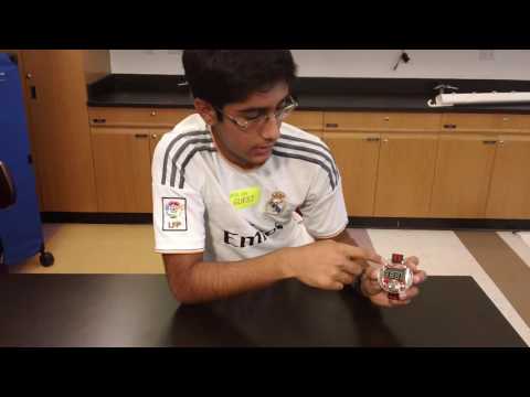
The Bigtime Watch uses 7 components to tell the time: 1 ATMega328 DIP IC microcontroller, 1 10kOhm resistor, 1 4-digit 7-segment LED display, 1 32kHz crystal, 1 20mm coin battery and holder, 1 right angle tactile button, and 2 0.1uF ceramic capacitors. The battery supplies voltage to the microcontroller and has an approximate batterylife of 2 years. The microcontroller starts counts vibrations from the crystal. When it counts 65,535 vibrations, the variable that counts seconds is increased by one. When 60 seconds passes the minute is increased by one. However, the display only shows the time when the button is pressed and released once. If the processor reads that the button is being held, it allows you to adjust the time by increasing the time by one minute at a time. After a few seconds, the adjustment increases by 10 minute intervals. The board also has the option to be reprogrammed by attaching a usb connection to the board. The input from the computer is filtered through a capacitor before going to the microcontroller.
To build this project I began by soldering all of the components to the board. I then plugged in the battery and tested the button to confirm that it all of the components were working properly. I then proceeded to attach the board to the housing of the watch. After laying all the parts in place, I screwed them together using four 4-40 screws. Next, I attached the watch band to the bottom of the housing. After testing the watch, I found that the button was getting jammed in the housing and was constantly adjusting the time. To solve this problem, I unscrewed the housing and re-screwed the parts back together. I retested the watch, and everything worked properly.