Introduction: Hi! My name is Sam, I am in the class of 2018 at the Heschel High School and I am at BlueStamp creating cool projects.
Reflection: When I came to BlueStamp I had very little prior knowledge about computer science and engineering. Through the 6 weeks that I have been here I have never had a better learning experience. I dislike lecture classrooms and usually learn very little in them. At BlueStamp it couldn’t be more the opposite. You want to learn something? Google’s there for a reason. You’re stuck? The instructors will guide you in the right direction. BlueStamp has revolutionized the learning process by grading you on your ability to actually do amazing things instead of the existing education system that judges you only on your theoretical knowledge and your ability to spit back information. BlueStamp has helped me in the process of teaching myself robotics and has given me a passion for not only learning more about it, but doing more projects. I learned a tremendous amount about electrical, mechanical, and computer engineering and I hope to come back next year!
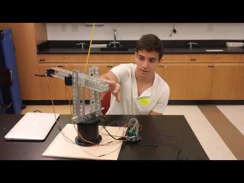
Final Explanation:
For my third milestone I have given my robot the ability to read an array of numbers, check to see if there are any 1’s in that 8X9 array (as opposed to 0’s) and then moves the servos in such a way that it reaches the physical points I represented with 1s. In order to figure out the positions that the servos are at while touching a certain point on the piece of paper I attached a wire to the servos’ potentiometers so that I can read and save those values in four 8x9 arrays. I went through all 72 points on the piece of paper and saved the values of all 4 servos at those positions. I then created a function called “loopthrough” that loops through an 8X9 grid of 0’s and 1’s. The way I search through that array is by implementing two for loops, the first to go through the arrays’s columns, the second to go through the values within those columns. Once I find the positions where the 1’s are located, I tell the servos to move to the positions of the 1’s in their own arrays(the arrays that I saved the positions of the four different servos at 72 different points). Therefore, the base is given the value of the 1’s position in the first array, the shoulder servos do the same with the second and third array, and the elbow repeats that process for the fourth array. Once it finds the exact values, I tell the servos to go to those positions, allowing it to paint a picture.
Final Video:
My Code:
Schematic:
https://drive.google.com/file/d/0Bz1mc_y-xTOZSlp0MzhtMlZBRUk/view?usp=sharing
Picture of Schematic:
https://drive.google.com/file/d/0Bz1mc_y-xTOZMlRRRkR6dTJSYjQ/view?usp=sharing
Hacking into 645 servos:

*solder a wire to the backside of the board onto the bright yellow wire
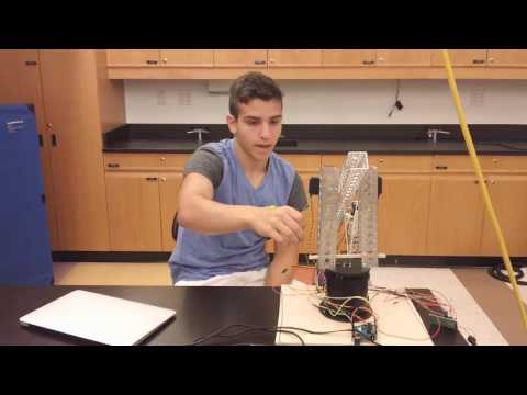
Second Milestone Explanation:
For my second milestone I gave the arm the ability to record its motions and then replay those motions so that it can paint. In order to do that I needed to give the arm another degree of freedom to give it a better range of motion. I accomplished that by putting another servo on the 15 inch aluminum shoulder and then attaching a 6 inch aluminum channel to that servo. To record the movements of the arm I hacked into all four servos and soldered a wire to the potentiometer within the servos to get their exact positions. Once I got those values from the potentiometer I needed to use the mapping function in Arduino to give the servos a readable value. I placed those values from the mapping function into a string, but I didn’t put them into an array because arrays are immutable and I wouldn’t know the exact length of each string I was recording. Lastly, I parse the string to get the values that the servos need to replay.
Issues:
A major issue I encountered was that the arm had incredibly jerky motions when trying to replicate the positions I gave to it.
Video:
Record and Replay code:
Future modifications:
I will give it much smoother motions by implementing a function that allows the arm to move in 1 degree increments until the servos reach their desired positions. I will also use bitmap and the record function to allow the arm to paint.
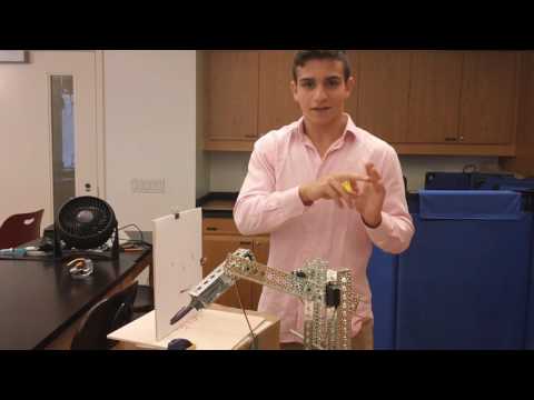
First Milestone Explanation:
Today I built a robotic arm. The arm has only two degrees of freedom right now allowing the arm to move up and down and side to side. The base is made out of a cylinder with a servo inside, the servo is connected to the platform of the arm so that the arm can move clockwise and counterclockwise. The arm, which is attached to the platform is made out of two 9” aluminum channels to hold the 15” channel which acts as an elbow. I attached two servos to the two 9” aluminum channels facing each other, they are both connected to 15” channel so that I am able to move the heavy weight of the 15” channel. At the end of the arm I have a gripper. The gripper is attached to a servo in such a way that when the servo reaches its max position the gripper opens and when the gripper reaches its min position it closes. The way I control the movement of the robot is by using a java program to read my keyboard. When I press the up arrow key Java sends a signal “U” to my Arduino code via serial communication, as a response the Arduino code sends a signal to the board to move both of servos connected to the 9” channels to move upwards. The other keys I used to control it were the down arrow key to move the two servos down, I used the left and right arrow keys to make the arm move counterclockwise and clockwise. Lastly, I used shift to make the arm open and control to close the gripper. To help the servos move the heavy 15” channel I placed a rubber band near the end of the 15” aluminum channel to counterbalance the weight.
Problems I Faced:
Some of the problems I encountered were trying to use a potentiometer to control the robot. The potentiometer was receiving so much noise that the arm would jiggle relentlessly. I tried to implement a low pass filter to reduce the jitter but nothing worked so I switched to using a Java program to control it. I also needed to make the motors that were facing each other go to supplementary angles in order to make sure that they were not fighting each other. Because they were facing each other, one motor being at 0 degrees would in turn mean that the other motor would need to be at 180 degrees to match its position.
This was the code I had when I was trying to control it with servos.
Future Modifications:
For my modifications on this project I will add another degree of freedom to to the arm so that I can improve my attempts to grab objects. I will also add flex sensors to a glove in order to control it with my hand. This is a link to my first milestone.
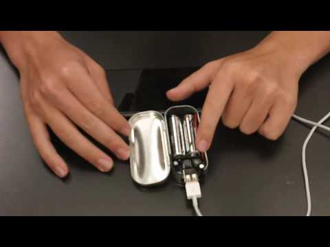
MintyBoost (starter project) Explanation:
Today I built a MintyBoost project. The goal of the MintyBoost is to convert 3V of power from 2 AA batteries into 5V of power to charge a phone. In order to do that I needed something called an inductor which has current passed through the coil wire inside of it to create a magnetic field. The microprocessor, the brain of the system, will open a switch-forcing the inductor to convert more magnetic energy into electrical energy sending 5V of electricity through a diode. The diode prevents the 5V from dropping by manipulating the electrons to go into one direction. There are several electrolytic capacitors that help maintain the input and output of the voltage. The resistors are limiting the current that passes through to the USB. The main issue I encountered when using the MintyBoost is that the container holding the components overheated. I realized that the current was flowing straight from the components into the surrounding metal case, resulting in overheating. This is shown in the equation for power-Power=V^2/R and considering the resistance of the metal case was practically 0, I was wasting massive amounts of energy. I put electrical tape inside the container, stopping the current from reaching the case, and ultimately stopped it from overheating. This is a link to my starter project.