
Wind Turbine
Engineer
Saimon K
Area of Interest
Computer Science/Electrical Engineering
School
Trinity School
Grade
Rising Senior
Reflection
BlueStamp was a great experience that I will cherish forever. Not only did I make a fully functional wind turbine and learn lots of specific material, but I also learned about myself and how I could grow. Before this program I had experience with mostly software and very little hardware. I entered the summer ready for a challenge, and I did indeed meet one. I threw myself into a hardware heavy project, and on top of that there was very sparse documentation and no helpful material guides. It was a struggle from the beginning but I found that this brought out the best in me. It made me spend every minute in a productive manner and it pushed me to work harder to achieve my goals. I found myself getting more comfortable with not knowing the answer right away, because sometimes there is no correct answer. Instead, I grew more accustomed to adapting to the situation and improvising. I would brainstorm different ways to overcome my challenges, plan them out and try them, and if that didn’t work I would come at the issue from a different direction. BlueStamp made me uncomfortable so I could grow: I thought more critically and I executed more efficiently. This program taught me that engineering, much like any discipline, is a process. I can’t expect to reach my full potential on my first day just like I can’t expect to finish a large task in one day. I have to break up the project and take it one day at a time just like I have to gradually improve my engineering skills. I have much more confidence in my own abilities to succeed since I can directly point to my procedure and my accomplishments in my documentation. It not only shows others what I accomplished but it is a physical manifestation of my knowledge and a constant reminder that I can tackle some of these complex obstacles and walk away the victor. However, independent success only has so much value. One of the greatest parts of BlueStamp was that I could share my daily experiences. In addition to discussing my project with my instructor, I also shared with a whole group of engineers who genuinely cared enough to hear me out just as I did them. As important as it was for me to work independently, I learned a great deal about the importance of communicating my process as well as results and supporting my peers so we can all succeed together.
Final Milestone
For my final milestone, I assembled the final portions of my wind turbine and connected to the electronics. I connected the gears to the generator to make sure it rotated and generated energy smoothly as shown in figure 3. Afterwards, I connected the generator and the rechargeable battery to the solar charge controller, which stabilizes input voltages, in order to properly store energy.
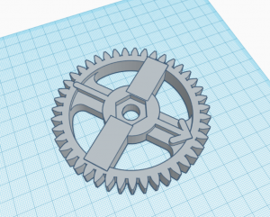
Figure 1: Large Gear TinkerCAD
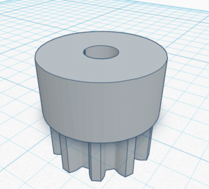
Figure 2: Small Gear TinkerCAD
I used two STL files from Vittorio Loschiavo in order to 3D print the two gear pieces I would need. I made some modifications to his designs to better fit my needs. First, I resized the two pieces so they would fit better on the metal rod and generator. Next, I added two solid radii on the larger gear, for a total of four, so it could be better attached to the spinning wooden piece which holds the fan blades together. Lastly, after experimenting with MakerBot, I realized a flat starting point is ideal for the item I want to print. Therefore, I created a “hole” object in TinkerCAD and used it to flatten out the bottom and make a more stable base for the larger gear.
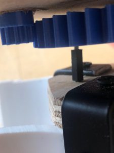
Figure 3: Connected gears
The large gear is placed on the threaded metal rod and is powered by the rotation of the fan blades. This gear is connected to the smaller gear which is attached to the generator, so the generator moves when the large gear moves. These two parts are crucial to harnessing wind energy that moves the blades into a portable form.
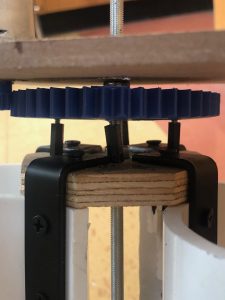
Figure 4: Large Gear Placement
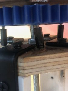
Figure 5: Standoffs
I drilled four holes in the wooden piece with the bearing as well as in the gear so that I could connect the two. I needed to attach the larger gear to the wooden piece because it has a bearing inside ensuring that it moves around the metal rod, which stays still. I used standoffs, screwing them into the wood and then placing screws through the holes in the gear into the standoffs.
One of the most difficult tasks was accurately drilling the holes in the proper positions while also holding the gear on a level plane and centering it on the rod since its diameter was larger. Although the level is not perfect because all human measurements have certain margins of error, I did my best to adjust the position of the gear as much as possible.
I attached the smaller gear to the generator so that it spun due to the movement of the larger gear, powering the generator. In order to have the small gear securely placed next to the larger gear, I designed a hole in some wood which would only allow the gear to go through to touch the larger gear. I then put that wood in the rod between two hex nuts which I tightened in order to secure the wood in place.
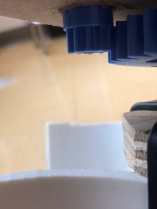
Figure 6: Small Gear Placement
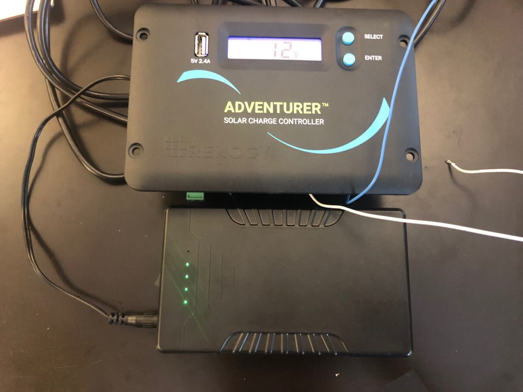
Figure 7: Solar Charge Controller and Battery
The solar charge controller regulates and stabilizes the input voltage so it can safely be outputted to a rechargeable battery even with unsteady and erratic inputs. The generator, essentially powered by the movement of the blades, is the input and the battery is where the voltage gets outputted.
Figure 8: Oscilloscope and Final Testing
The oscilloscope shows the voltages produced from the wind turbine without affecting the output. In the video, you can see that as the blades move, the voltages output by the turbine aren’t always steady but they are being read which means the generator is functioning properly. This further establishes the importance of the solar charge controller as it regulates these varying voltages in order to safely store the energy.
By completing this milestone, I essentially finished my whole project. I now have a functioning wind turbine that can store energy. Although it may not be the most efficient, in terms of cost or functionality, the fact that it actually works is incredible and the overall process was very valuable. I learned a lot about design and construction as well as the electronics behind storing energy. Although I ran into many obstacles, such as not having properly fitted parts and struggling to attain maximum precision when attaching certain parts, I learned how to work around issues and have confidence in my abilities to adapt. Completing this project on my own and planning out my own steps have allowed me to be more independent and increase how efficiently I work. I now have confidence that I can independently pursue my interests in this field and push myself outside of my comfort zone in order to learn more and develop my problem solving skills.
Milestone 2
For my second milestone, I focused on the design, part acquisition, and initial fabrication and part modification for the wind turbine. However, before I could do any of this I created a couple of CADs and detailed designs so I could accurately assess the parts I would need.
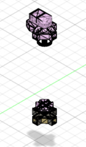
Figure 1: CAD of originally 3D printed parts
The original project designer, Vittorio Loschiavo, 3D printed the parts shown above in figure 1 and saved each as an STL file open to the public. I downloaded all the files and opened them in one project sheet and arranged them into their proper positions to create the final product. This gave me a more practical view of the specific mechanics of all the parts and how they would be assembled.
Realizing the limitations and nuisances of 3D printing, I decided it might be more efficient to rely on hand-made parts in place of some of the simple parts. I set out to create my own variations of some of his parts out of wood in order to avoid long printing times and various trials.
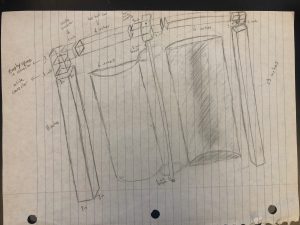
Figure 2: Initial Sketch
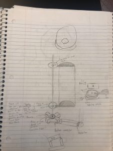
Figure 3: Sketch with Wooden Pieces
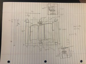
Figure 4: Full Sketch
I decided to take a more classic approach, pencil and paper, after Fusion proved to be too much for my laptop to handle. I reverted to detailed sketches and diagrams as seen in figures 2-4. These designs allowed me to be more dynamic with visual detail by exaggerating important elements and also pay close attention to measurements and specific building concerns.
I had to cut square metal bars into certain dimensions so I could create a frame. With limited resources, I made the most out of a handsaw. After painstakingly sawing for many days, I finally had the right dimensions for the pieces of the frame.
Despite accomplishing the above, I ran into a frustrating issue. The 1-inch plastic connectors I received did not fit into the 1-inch square aluminum bars. In an effort to be resourceful and not waste supplies, I used a Dremel to shave down the connectors by burning off layers of plastic until they would match the bars. After hours of diligence, I was successful.
I also cut PVC pipes to make four fan blades to catch the wind. I intentionally used this heavier material because it was sturdy yet not too massive. The PVC thickness and strength allowed for the fan blades to easily catch wind and smoothly carry on motion.

Figure 5: Bill of materials
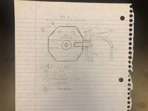
Figure 6: Sketch of bearing housing
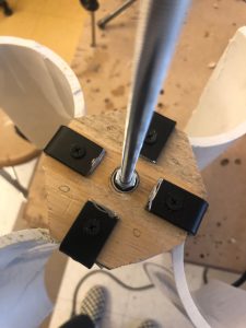
Figure 7: Wooden pieces with bearings (top view)
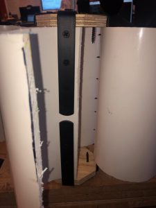
Figure 8: Wooden pieces with brackets (side view)
I needed a structure that could securely support four PVC blades, ensure stabilized positions, and facilitate smooth rotational movement around one specific point. At first, I thought about making wooden pieces with bearings inside that would allow for rotation around the metal rod. This idea evolved into octagonal wooden pieces that would hold a bearing and attach to a metal bracket, which would be screwed into a top and bottom wooden piece along with fan blade in order to stabilize and level all of them.
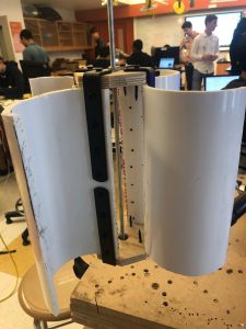
Figure 9: Finished fan blade structure
I created the wooden pieces and then drilled four holes for the four brackets, one for each fan blade. After adjusting the size of the brackets by cutting off excess, I attached them to the wooden pieces and then marked the necessary holes in the PVC pipes in order to place screws there, as shown in figure 8. I drilled these holes, making them slightly smaller than the screw radius so the screws were a tight fit and had no chance of coming out.
After attaching all the parts, I filed down some of the screws and put caps on others. I also placed a lock nut at the bottom of the rod so this section with the blades would not fall off or veer off course. Lastly, I tested it and the movement was very smooth and flawless.
My second milestone was a big one, requiring me to tackle various engineering processes in addition to the actual physical construction. I made lots of sketches and diagrams to plan out every specific element in order to ensure the greatest level of precision and accuracy. Modifying these plans was a given and turned out to be crucial as I ran into obstacles and logistical issues. In addition, I modified my parts for much of my time. Without parts of the right dimensions easily available, I learned to adapt and make the most of my supplies. Lastly, I gained experience physically putting together all these components that should theoretically work together. As a result of inevitable compatibility issues, I learned to think outside the box and improvise in order to still accomplish my goals.
Milestone 1
My main project is a wind turbine, but before I delved into that project I began with a proof of concept. For my first milestone, I started by creating a MintyBoost, a battery powered USB charger. Then, I modified this device so it could use a wind powered generator as the power source instead of double A batteries.
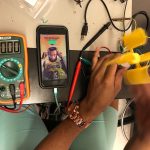
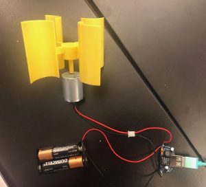
Figure 1: Completed MintyBoost
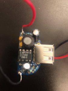
Figure 2: Soldered parts on PCB
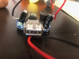
Figure 3: MintyBoost front view
Initially, I created a MintyBoost using a PCB (printed circuit board), two double A battery holder, USB type A jack, power inductor, diodes, resistors, bypass capacitors, power supply capacitors, 8-pin socket, and 5V boost converter. I soldered all these parts onto the PCB.
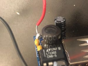
Figure 4: Power inductor
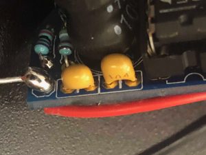
Figure 5: Ceramic capacitors
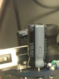
Figure 6: Electrolytic capacitors
Two of the most important elements of this device are the power inductor and capacitor. The inductor stores electrical energy in magnetic form by creating a magnetic field where electricity wraps around its coil. It converts lower DC (direct current) voltages to higher ones, meaning it conducts best at lower frequencies, because of the boost converter setup. The capacitor stores energy in an electric field. It can store energy when the MintyBoost is working, and when it is off the capacitor can release the stored energy, serving as a temporary battery. Capacitors are necessary because they stabilize the output voltage by filtering out high frequency noise. As a result, the voltage is more clear and consistent.
I attached a schottky diode because it controls the flow of energy. A special quality of diodes is that energy can flow in only one direction. This way I can clearly differentiate between the input (power source) and output (item being charged). In particular, a schottky diode also maintains a specific voltage, acting as a pseudo voltage regulator.
The boost converter increases voltage while decreasing current.
I connected the red and black wires from the battery holder to the positive and negative poles on the PCB. Once I put the batteries in and plugged an iPhone charger into the MintyBoost, my iPhone was charging which shows the energy from the batteries is correctly being outputted.
After finishing the MintyBoost, I wanted to make use of a DC motor with blades. The motor would convert mechanical energy, fueled manually or ideally by the wind, into electrical energy.
At first, I soldered the red and black wires from the motor to those on a USB I cut open so I could plug it into the USB type A jack. I had hoped that the motor would charge the batteries. However, the motor started moving, which was a clear indication that the batteries were powering it. In order to test if the motor was giving any energy, I connected a multimeter to the input. A multimeter is an electronic measuring instrument that can measure voltage, current, and resistance. The batteries clearly sent out a voltage, and so did the motor once I turned the blades. The voltage from the motor was very small and negative, leading me to hypothesize that the outputted energy from the batteries overpowered that from the motor. In addition, I had overlooked the power of the schottky diode to regulate the direction of energy flow.
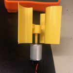
Figure 7: Motor with blades
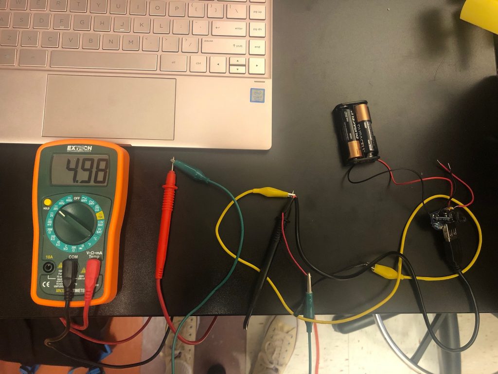
Figure 8: Multimeter with batteries
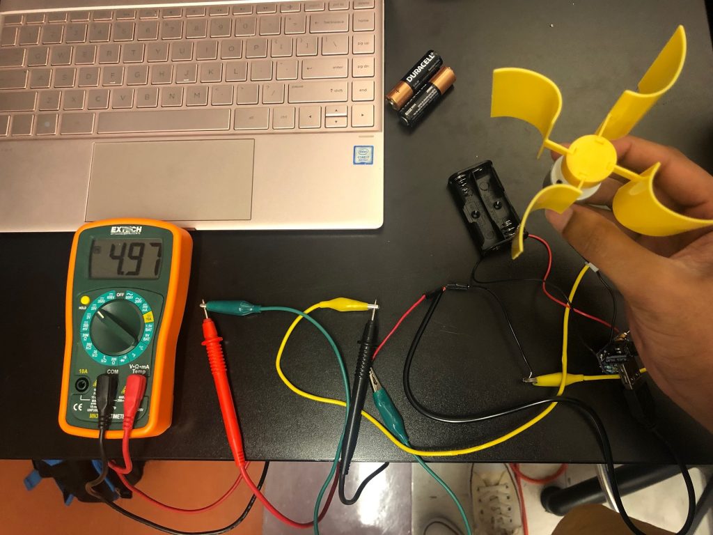
Figure 9: Multimeter with motor
Afterwards, I made the motor my input by soldering its wires to the proper poles on the PCB. I took out the batteries so the motor would be the only source of energy. Then, when I plugged in my charger and spun the blades on the motor, I saw my phone charging. Also, when I connected the multimeter to the output, the motor gave off a steady 5V when operating at a reasonable speed which indicated that it was functioning properly.
My first milestone helped me learn more about the actual parts that would go into generating, storing, and efficiently releasing energy which relate to my main goal of creating a wind turbine. It was helpful working with a motor now because I’ll be using a larger one later on. I got more practice soldering which is always a positive. I also did a good deal of troubleshooting where I used the multimeter to isolate individual parts’ performances as I analyzed their specific functions in order to pinpoint the issue.
Starter Project
My starter project is the motion alarm system. The motion alarm is a small device that can detect motion and output noise, lights, and movement in turn. This project is modeled after Sparkfun’s “Circuit 3C: Motion Alarm.” (See the code from Sparkfun at the bottom) I enjoyed completing this project because I gained more insight on incorporating sensors with Arduino while creating a practical apparatus on a smaller scale.
Demonstration
How it works
The motion alarm includes an Arduino Uno, a distance sensor, a piezo buzzer, a servo, and LEDs (light-emitting diodes). Arduino Uno is a microcontroller board with input and output pins which can be extended to a breadboard in order to create a circuit with various functions. The distance sensor determines how close an object is. The piezo buzzer creates a beeping noise. The servo controls rotary motions in order to create precise movement.
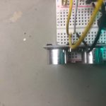
Figure 1: Motion Sensor Top View
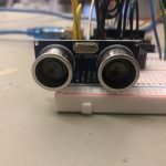
Figure 2: Motion Sensor Front View
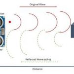
Figure 3: Echo and Trigger Diagram (from RandomNerdTutorials)
Pins 11 and 12 connect to Echo and Trigger, respectively. Trigger is responsible for sending out a ping, and Echo receives it after the ping bounces off the nearest object. The motion sensor determines how close an object is by recording how long it takes for the ping to return. In the code, Trigger sends out an ultrasonic pulse and the pulseIn command incorporates Echo to find out how long it took the pulse to return. I used a simple equation with the sensor data: distance = speed * time. Therefore, if it takes longer for the ping to come back then the distance must be greater since the speed is a constant. The last two pins I used on the Uno were the VCC, which powers my system with 5V, and the Ground, which maintains the flow of electricity.
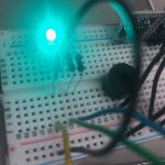
Figure 4: Piezo Buzzer
The piezo buzzer is connected to ground for power and also pin 10 which is a PWM (pulse width modulation) pin that can control the amount of buzzing. PWM sends out a series of pulses which allows for a smooth stream of commands to be carried out while limiting the amount of current. Since Arduino can only send out 5V, PWM establishes a new average power by controlling the duty cycle, how long the set voltage is sent and how long there is no voltage.
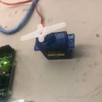
Figure 5: Servo
The servo is connected to ground, 5V power, and pin 9 which controls the movement of the servo. PWM is useful because the series of pulses that it sends out allows for multiple motions to be triggered by the motor so the object attached above can continue moving.
The LEDs are controlled by pins 3, 5, and 6, which are all PWM pins. This way the alpha channel, or opacity, of each color can be controlled by a number between 0 and 255.
The resistors limit the current that goes to the LEDs.
The longer, positive sides of the LEDs are controlled by these pins, and the shorter, negative sides of the LEDs are connected to ground in order to maintain the proper flow of electricity and avoid a short circuit.
In order to determine when to activate these colors, noises, and movements the code included if statements to control different scenarios. The distance was calculated by using the distance equation and setting speed as a constant and recording the time for the signals to be reflected back. The LED was supposed to be colored red if the distance was less than 10 inches, yellow between 10 and 20, and green when greater than 20. There would only be noise and movement for objects within 10 inches. I did not have a 4 pin RGB LED, so instead I used 3 different LEDs, a red, green, and blue one. It’s the same concept, but the only issue is that for yellow (between 10 and 20 inches), red and green flicker on at the same time because the colors are separated instead of combining different amounts to attain yellow.
I learned a great deal about using sensors with Arduino and also how to take specific data or inputs and create specialized outputs.
Motion Alarm Schematic

#include                 //include the servo library
const int trigPin = 11; //connects to the trigger pin on the distance sensor
const int echoPin = 12; //connects to the echo pin on the distance sensor
const int redPin = 3; //pin to control the red LED inside the RGB LED
const int greenPin = 5; //pin to control the green LED inside the RGB LED const int bluePin = 6; //pin to control the blue LED inside the RGB LED
const int buzzerPin = 10; //pin that will drive the buzzer float distance = 0; //stores the distance measured by the distance sensor Servo myservo; //create a servo object

void setup() {
Serial.begin (9600); //set up a serial connection with the computer
pinMode(trigPin, OUTPUT); //the trigger pin will output pulses of electricity
pinMode(echoPin, INPUT); //the echo pin will measure the duration of pulses coming back from the distance sensor //set the RGB LED pins to output
pinMode(redPin, OUTPUT); pinMode(greenPin, OUTPUT); pinMode(bluePin, OUTPUT); pinMode(buzzerPin, OUTPUT); //set the buzzer pin to output
myservo.attach(9); //use pin 9 to control the servo
}
void loop() {
distance = getDistance(); //variable to store the distance measured by the sensor
Serial.print(distance); //print the distance that was measured
Serial.println(" in"); //print units after the distance
if(distance <= 10){ //if the object is close
//make the RGB LED red
analogWrite(redPin, 255);
analogWrite(greenPin, 0);
analogWrite(bluePin, 0);
//this code wiggles the servo and beeps the buzzer
tone(buzzerPin, 272); //buzz the buzzer pin
myservo.write(45); //move the servo to 45 degrees
delay(100); //wait 100 milliseconds
noTone(buzzerPin); //turn the buzzer off
myservo.write(135); //move the servo to 135 degrees
delay(100); //wait 100 milliseconds
}
else if(10 < distance && distance < 20){ //if the object is a medium distance
//make the RGB LED yellow
analogWrite(redPin, 255);
analogWrite(greenPin, 50);
analogWrite(bluePin, 0);
}
else{ //if the object is far away
//make the RGB LED green
analogWrite(redPin, 0);
analogWrite(greenPin, 255);
analogWrite(bluePin, 0);
}
delay(50); //delay 50ms between each reading }
//------------------FUNCTIONS----------------------------- – //RETURNS THE DISTANCE MEASURED BY THE HC-SR04 DISTANCE SENSOR
float getDistance() {
float echoTime; //variable to store the time it takes for a ping to bounce off an object
float calculatedDistance; //variable to store the distance calculated from the echo time
//send out an ultrasonic pulse that's 10ms long
digitalWrite(trigPin, HIGH);
delayMicroseconds(10);
digitalWrite(trigPin, LOW);
echoTime = pulseIn(echoPin, HIGH); //use the pulsein command to see how long it takes for the
//pulse to bounce back to the sensor
calculatedDistance = echoTime / 148.0; //calculate the distance of the object that reflected the pulse (half the bounce time multiplied by the speed of sound)
return calculatedDistance; //send back the distance that was calculated
}