Hi, my name is Robert, and I am a rising freshman at The Urban School of San Francisco. I came to Bluestamp because of my passion for building and creating things. The summers prior to this, I did some camps which involved engineering and building robots. My older brother previously went through Bluestamp and from the first time I watched his presentation, I knew I wanted to be in the program. I enjoy engineering because it allows me to be by myself, focusing on just my project without other distractions around me. When I build stuff at home, it is an escape from school and other things in my life. I spent my earlier years building with Legos and Conex, which peaked my interest in building and creating things. This summer in Bluestamp, for my starter project, I am building a TV controller which uses infrared LEDs to communicate with any TV in able to turn it on and off. My main project is a keypad and fingerprint scanning safe.
Reflection
These six weeks have gone by in a heartbeat. I didn’t know what to expect when I entered into this program besides the things that my brother told me when he did it. I see my other friends on vacation and sleeping in, and as much as I wish that I got a little more sleep, I wouldn’t have traded these six weeks for any other vacation or camp. I came into this program with some programming and engineering experience but nothing compared to what I learned here. I didn’t know how to properly get around problems and document what I have done. At home, I only made projects that were simple and came directly from instructions. After these six weeks, I now have a working keypad and fingerprint scanning safe and a better understanding of how to solve problems and map out my work.
A discovery that will really impact my future in engineering is that all problems have a solution that you can come up with. Before this program, I gave up really easily when a part didn’t work or something happened to my project. Now, the teachers have given me the tools and confidence to solve the problem on my own with minimal help from other people. Many times in the program, I came upon a problem in my work. In the beginning, I had no idea what to do besides asking the teachers to help, but slowly I got better at solving the problems. Even if I needed their help in the end, the process before asking them for help brought me closer to the solution and understanding how to solve the problem.
Throughout BSE, we had guest speakers come to talk to us about what they do in the field of engineering and to give us advice about starting a company, going to college, and other important components of engineering. Out of all of the speakers, I really enjoyed Arjun talk about his experiences in nanotech and his product which transformed touch screens and his antibacterial nanoparticle technology. I felt more connected with this company compared to the other people who talked. I definitely would like to make some sort of medical product if I come back to Bluestamp next summer. After BSE I still want to do engineering, but I would like to do something related to medicine.
Final Video
My final project in Bluestamp is the keypad and fingerprint scanning safe. This project allows for more security when trying to get into something. With multiple components to pass before opening the box, it would be nearly impossible for other people to get inside. I chose this project because it had a balance of coding and wiring components. Before this program, I felt pretty confident in my building skills, so I wanted to improve my programming skills with this cool and interesting project.
This project can be broken down into three parts. The keypad, the fingerprint scanner, and the servo. The first step in the process of opening the safe is the fingerprint scanner. You first have to upload the example code for enrolling fingerprints onto the scanner. You enroll however many fingerprints you want with different ID numbers. When you put your finger on the scanner, it reads your fingerprint with a confidence reading. If you place it firmly in the correct place, the confidence reading will be higher; if only half of your finger is on the scanner, the confidence number is lower. In the code, the Arduino tells the fingerprint scanner to only accept fingerprints with a confidence of over 150. If it reads the correct image, then the green light will blink.
The second part of the safe is the keypad. Inside of the keypad, each row and column have a single strip of wire running up and down, carrying current. When none of the keys are being pressed, the circuit has gaps. When you press a button, it completes the circuit and the computer reads that there is a connection between the certain pins. I didn’t know that you had to test which pins connect with which key. There are 4 rows and 3 columns. You put the multimeter on two of the pins and if there is a current, those two pins activate a key. I touched the probes of the multimeter to any of the two pins on the keypad. I then found the key on the keypad that made the multimeter beep and wrote it down. For example: pins 1 and 2 would correspond to key 3. I did this for all of the keys. Once I found all of the combinations, I found the common pin for each row and column and wrote that number down. Once that was done, I labeled the pins on the keypad as corresponds to the numbers that I wrote down next to the rows and columns. This was important because it taught me how to use a multimeter, and it taught me how to test where current was flowing. This part was definitely the hardest part to understand in this section, but it was very satisfying once I figured out how to go about solving it. Once you put the correct code in, the green led will blink; if wrong, the red will blink. This step will activate the next part of the safe.
The servo will turn once the correct password is put in. The servo was pretty easy to understand and code but also really fun because you can personalize what you want the servo to do and how it moves. In my situation, it starts parallel to the side of the box and moves 90 degrees to unattach from the L bracket on the top of the box, unlocking the box. It will wait 5 seconds and then will turn back around 90 degrees to the starting position to relock the box.
In my final milestone, I connected all of the different components in my project: the keypad, fingerprint scanner, and the servo. I had each part working correctly by itself, but I had some problems putting them all together. It was hard to keep track of everything, because I had a lot of lines of code to work with. What helped me was commenting on the side of some of the lines to understand what was going on in each section. It also helped me to plan out what I have to do and what the code will do before I even started to write anything. I could make a plan on what I had to get done and what I will do which made it easier to know what to write and get done. Before I chose this project, I wanted to learn more about programming, which this step taught me the most. I understood where to put the different parts and how to set up the code before starting. The code writing and getting past problems are still hard for me, but I definitely improved a lot. For future modifications, I have attached a switch and a speaker that plays a tune when you open the box. I also put in a case for the power source and a hole, so I can take it out if it loses charge. The tune is activated after the servo is turned, indicating that it is the end of the of the sketch.
This is the complete code that I used for my project. At the top of the code, it has a long set of #define NOTE comands. This defines and sets up the different keys and tones for the mario theme song.
#define NOTE_B0 31
#define NOTE_C1 33
#define NOTE_CS1 35
#define NOTE_D1 37
#define NOTE_DS1 39
#define NOTE_E1 41
#define NOTE_F1 44
#define NOTE_FS1 46
#define NOTE_G1 49
#define NOTE_GS1 52
#define NOTE_A1 55
#define NOTE_AS1 58
#define NOTE_B1 62
#define NOTE_C2 65
#define NOTE_CS2 69
#define NOTE_D2 73
#define NOTE_DS2 78
#define NOTE_E2 82
#define NOTE_F2 87
#define NOTE_FS2 93
#define NOTE_G2 98
#define NOTE_GS2 104
#define NOTE_A2 110
#define NOTE_AS2 117
#define NOTE_B2 123
#define NOTE_C3 131
#define NOTE_CS3 139
#define NOTE_D3 147
#define NOTE_DS3 156
#define NOTE_E3 165
#define NOTE_F3 175
#define NOTE_FS3 185
#define NOTE_G3 196
#define NOTE_GS3 208
#define NOTE_A3 220
#define NOTE_AS3 233
#define NOTE_B3 247
#define NOTE_C4 262
#define NOTE_CS4 277
#define NOTE_D4 294
#define NOTE_DS4 311
#define NOTE_E4 330
#define NOTE_F4 349
#define NOTE_FS4 370
#define NOTE_G4 392
#define NOTE_GS4 415
#define NOTE_A4 440
#define NOTE_AS4 466
#define NOTE_B4 494
#define NOTE_C5 523
#define NOTE_CS5 554
#define NOTE_D5 587
#define NOTE_DS5 622
#define NOTE_E5 659
#define NOTE_F5 698
#define NOTE_FS5 740
#define NOTE_G5 784
#define NOTE_GS5 831
#define NOTE_A5 880
#define NOTE_AS5 932
#define NOTE_B5 988
#define NOTE_C6 1047
#define NOTE_CS6 1109
#define NOTE_D6 1175
#define NOTE_DS6 1245
#define NOTE_E6 1319
#define NOTE_F6 1397
#define NOTE_FS6 1480
#define NOTE_G6 1568
#define NOTE_GS6 1661
#define NOTE_A6 1760
#define NOTE_AS6 1865
#define NOTE_B6 1976
#define NOTE_C7 2093
#define NOTE_CS7 2217
#define NOTE_D7 2349
#define NOTE_DS7 2489
#define NOTE_E7 2637
#define NOTE_F7 2794
#define NOTE_FS7 2960
#define NOTE_G7 3136
#define NOTE_GS7 3322
#define NOTE_A7 3520
#define NOTE_AS7 3729
#define NOTE_B7 3951
#define NOTE_C8 4186
#define NOTE_CS8 4435
#define NOTE_D8 4699
#define NOTE_DS8 4978#define melodyPin A1
int musicPlayed = 0;//Mario main theme melody
int melody[] = {
NOTE_E7, NOTE_E7, 0, NOTE_E7,
0, NOTE_C7, NOTE_E7, 0,
NOTE_G7, 0, 0, 0,
NOTE_G6, 0, 0, 0,//NOTE_C7, 0, 0, NOTE_G6,
//0, 0, NOTE_E6, 0,
//0, NOTE_A6, 0, NOTE_B6,
//0, NOTE_AS6, NOTE_A6, 0,
//NOTE_G6, NOTE_E7, NOTE_G7,
//NOTE_A7, 0, NOTE_F7, NOTE_G7,
//0, NOTE_E7, 0, NOTE_C7,
//NOTE_D7, NOTE_B6, 0, 0,
//NOTE_C7, 0, 0, NOTE_G6,
//0, 0, NOTE_E6, 0,
//0, NOTE_A6, 0, NOTE_B6,
//0, NOTE_AS6, NOTE_A6, 0,
//NOTE_G6, NOTE_E7, NOTE_G7,
//NOTE_A7, 0, NOTE_F7, NOTE_G7,
//0, NOTE_E7, 0, NOTE_C7,
//NOTE_D7, NOTE_B6, 0, 0
};
//Mario main them tempo
int tempo[] = {
12, 12, 12, 12,
12, 12, 12, 12,
12, 12, 12, 12,
12, 12, 12, 12,
12, 12, 12, 12,
12, 12, 12, 12,
12, 12, 12, 12,
12, 12, 12, 12,
9, 9, 9,
12, 12, 12, 12,
12, 12, 12, 12,
12, 12, 12, 12,
12, 12, 12, 12,
12, 12, 12, 12,
12, 12, 12, 12,
12, 12, 12, 12,
9, 9, 9,
12, 12, 12, 12,
12, 12, 12, 12,
12, 12, 12, 12,
};
//Underworld melody
int underworld_melody[] = {
NOTE_C4, NOTE_C5, NOTE_A3, NOTE_A4,
NOTE_AS3, NOTE_AS4, 0,
0,
NOTE_C4, NOTE_C5, NOTE_A3, NOTE_A4,
NOTE_AS3, NOTE_AS4, 0,
0,
NOTE_F3, NOTE_F4, NOTE_D3, NOTE_D4,
NOTE_DS3, NOTE_DS4, 0,
0,
NOTE_F3, NOTE_F4, NOTE_D3, NOTE_D4,
NOTE_DS3, NOTE_DS4, 0,
0, NOTE_DS4, NOTE_CS4, NOTE_D4,
NOTE_CS4, NOTE_DS4,
NOTE_DS4, NOTE_GS3,
NOTE_G3, NOTE_CS4,
NOTE_C4, NOTE_FS4, NOTE_F4, NOTE_E3, NOTE_AS4, NOTE_A4,
NOTE_GS4, NOTE_DS4, NOTE_B3,
NOTE_AS3, NOTE_A3, NOTE_GS3,
0, 0, 0
};
//Underwolrd tempo
int underworld_tempo[] = {
12, 12, 12, 12,
12, 12, 6,
3,
12, 12, 12, 12,
12, 12, 6,
3,
12, 12, 12, 12,
12, 12, 6,
3,
12, 12, 12, 12,
12, 12, 6,
6, 18, 18, 18,
6, 6,
6, 6,
6, 6,
18, 18, 18, 18, 18, 18,
10, 10, 10,
10, 10, 10,
3, 3, 3
};
///////////////////^MARIO SET UP^////////////////////////////////
#include
#include #include
#include
#include
Servo myservo;
int pos = 80;
int getFingerprintIDez();
SoftwareSerial mySerial(2, 3);
Adafruit_Fingerprint finger = Adafruit_Fingerprint(&mySerial);
Password password = Password(“1219”); //sets password
int ledPin = 10;//sets leds
int ledPin2 = 11;
int ledPin3 = 12;
int ledPin4 = 13;
uint8_t p;
bool correctPassword;
const byte ROWS = 4;
const byte COLS = 3;
char keys[ROWS][COLS] = {
{‘1′,’2′,’3’},
{‘4′,’5′,’6’},
{‘7′,’8′,’9’},
{‘*’,’0′,’#’}
};
byte rowPins[ROWS] = {8, 3, 4, 6};
byte colPins[COLS] = {7, 9, 5};
Keypad keypad = Keypad( makeKeymap(keys), rowPins, colPins, ROWS, COLS );
void setup(){
while (!Serial);
Serial.begin(9600);
Serial.println(“Adafruit finger detect test”);
pinMode(10,OUTPUT);
pinMode(11,OUTPUT);
pinMode(12,OUTPUT);
pinMode(13,OUTPUT);
finger.begin(57600);
myservo.attach(A0);
pinMode(A1, OUTPUT);//buzzer
pinMode(13, OUTPUT);//led indicator when singing a note
if (finger.verifyPassword()) {
Serial.println(“Found fingerprint sensor!”);
} else {
Serial.println(“Did not find fingerprint sensor :(“);
while (1);
}
Serial.println(“Waiting for valid finger…”);
//getFingerprintID();
keypad.addEventListener(keypadEvent);
/*Serial.print(“Type your password to enter!\n\n”);
Serial.print(“Pressed: “);
pinMode(ledPin,OUTPUT);
digitalWrite(ledPin,LOW);
pinMode(ledPin2,OUTPUT);
digitalWrite(ledPin2,LOW);
//myservo.attach(11);
*/
}
void loop(){
//keypad.getKey();
//checkPassword();
//getFingerprintIDez();
if(!correctPassword) {
getFingerprintID(); // gets the finger print id’s
}
if(correctPassword) {
keypad.getKey(); //reads that keys are being pressed
//checkPassword();
}
}
void keypadEvent(KeypadEvent eKey){
switch (keypad.getState()){
case PRESSED:
switch (eKey){
case ‘*’: checkPassword(); break;
case ‘#’: password.reset();Serial.print(“\nPressed: “);break;
default: password.append(eKey); Serial.print(eKey);
}
}
}
void checkPassword(){
//if (p == FINGERPRINT_OK) { // first step: fingerprint scanner
digitalWrite(10,HIGH);
digitalWrite(10,LOW);
digitalWrite(13,HIGH);
delay(1000);
digitalWrite(13,LOW);
delay(1000);
digitalWrite(10,HIGH);
Serial.print(“Found ID #”); Serial.print(finger.fingerID);
Serial.print(” with confidence of “); Serial.println(finger.confidence);
if (password.evaluate()){ // second: password
Serial.println(“\nSuccess!!!”);
digitalWrite(12,HIGH);
digitalWrite(12,LOW);
digitalWrite(11,HIGH);
delay(1000);
digitalWrite(11,LOW);
delay(1000);
digitalWrite(12,HIGH);
//getFingerprintIDez();
//delay(50);
//digitalWrite(12,HIGH);
for (pos = 80; pos <= 170; pos += 10) { // goes from 120 degrees to 30 degrees Serial.print(“got here”); myservo.write(pos); // tell servo to go to position in variable ‘pos’ delay(100); // waits 15ms for the servo to reach the position } if (musicPlayed == 0){ //play mario sing(1); musicPlayed = 1; } delay(5000); for (pos = 170; pos >= 80; pos -= 5) { // goes from 90 degrees to 0 degrees
myservo.write(pos); // tell servo to go to position in variable ‘pos’
delay(100); }
delay(5000);
}
else{
Serial.println(“\n\nWrong password”);
digitalWrite(ledPin2,HIGH);
delay(4000);
digitalWrite(ledPin2,LOW);
password.reset();
Serial.print(“\nPressed: “);
}
}
int getFingerprintIDez() {
Serial.print(“Getting fingerprint”);
p = finger.getImage();
if (p != FINGERPRINT_OK) return -1;
p = finger.image2Tz();
if (p != FINGERPRINT_OK) return -1;
p = finger.fingerFastSearch();
if (p != FINGERPRINT_OK) return -1;
// found a match!
Serial.print(“got here2”);
digitalWrite(12,LOW);
digitalWrite(11,HIGH);
delay(1000);
digitalWrite(12,HIGH);
digitalWrite(11,LOW);
delay(1000);
//put servo code
for (pos = 30; pos <= 120; pos += 10) { // goes from 0 degrees to 90 degrees // in steps of 1 degree myservo.write(pos); // tell servo to go to position in variable ‘pos’ delay(100); // waits 15ms for the servo to reach the position } delay(5000); for (pos = 120; pos >= 30; pos -= 5) { // goes from 90 degrees to 0 degrees
myservo.write(pos); // tell servo to go to position in variable ‘pos’
delay(100); // waits 15ms for the servo to reach the position
}
delay(5000);
Serial.print(“Found ID #”); Serial.print(finger.fingerID);
Serial.print(” with confidence of “); Serial.println(finger.confidence);
return finger.fingerID;
if (musicPlayed == 0){ // play mario
sing(1);
musicPlayed = 1;
}
}
uint8_t getFingerprintID() {
uint8_t p = finger.getImage();
switch (p) {
case FINGERPRINT_OK:
Serial.println(“Image taken”);
break;
case FINGERPRINT_NOFINGER:
Serial.println(“No finger detected”);
return p;
case FINGERPRINT_PACKETRECIEVEERR:
Serial.println(“Communication error”);
return p;
case FINGERPRINT_IMAGEFAIL:
Serial.println(“Imaging error”);
return p;
default:
Serial.println(“Unknown error”);
return p;
}
// OK success!
p = finger.image2Tz();
switch (p) {
case FINGERPRINT_OK:
Serial.println(“Image converted”);
break;
case FINGERPRINT_IMAGEMESS:
Serial.println(“Image too messy”);
return p;
case FINGERPRINT_PACKETRECIEVEERR:
Serial.println(“Communication error”);
return p;
case FINGERPRINT_FEATUREFAIL:
Serial.println(“Could not find fingerprint features”);
return p;
case FINGERPRINT_INVALIDIMAGE:
Serial.println(“Could not find fingerprint features”);
return p;
default:
Serial.println(“Unknown error”);
return p;
}
// OK converted!
p = finger.fingerFastSearch();
if (p == FINGERPRINT_OK) {
Serial.println(“Found a print match!”);
} else if (p == FINGERPRINT_PACKETRECIEVEERR) {
Serial.println(“Communication error”);
return p;
} else if (p == FINGERPRINT_NOTFOUND) {
Serial.println(“Did not find a match”);
return p;
} else {
Serial.println(“Unknown error”);
return p;
}
// found a match!
correctPassword = true;
digitalWrite(10,LOW);
digitalWrite(13,HIGH);
delay(1000);
digitalWrite(13,LOW);
delay(1000);
digitalWrite(10,HIGH);
//servo code
/*for (pos = 50; pos <= 30; pos += 10) { // goes from 0 degrees to 90 degrees // in steps of 1 degree myservo.write(pos); // tell servo to go to position in variable ‘pos’ delay(100); // waits 15ms for the servo to reach the position } delay(5000); for (pos = 30; pos >= 50; pos -= 5) { // goes from 90 degrees to 0 degrees
myservo.write(pos); // tell servo to go to position in variable ‘pos’
delay(100); // waits 15ms for the servo to reach the position
}
Serial.println(“hi”);
*/
return finger.fingerID;
Serial.print(“Found ID #”); Serial.print(finger.fingerID);
Serial.print(” with confidence of “); Serial.println(finger.confidence);
}
//////////////mario set up//////////////////
int song = 0;
void sing(int s) {
// iterate over the notes of the melody:
song = s;
if (song == 2) {
Serial.println(” ‘Underworld Theme'”);
int size = sizeof(underworld_melody) / sizeof(int);
for (int thisNote = 0; thisNote < size; thisNote++) {
// to calculate the note duration, take one second
// divided by the note type.
//e.g. quarter note = 1000 / 4, eighth note = 1000/8, etc.
int noteDuration = 1000 / underworld_tempo[thisNote];
buzz(melodyPin, underworld_melody[thisNote], noteDuration);
// to distinguish the notes, set a minimum time between them.
// the note’s duration + 30% seems to work well:
int pauseBetweenNotes = noteDuration * 1.30;
delay(pauseBetweenNotes);
// stop the tone playing:
buzz(melodyPin, 0, noteDuration);
}
} else {
Serial.println(” ‘Mario Theme'”);
int size = sizeof(melody) / sizeof(int);
for (int thisNote = 0; thisNote < size; thisNote++) {
// to calculate the note duration, take one second
// divided by the note type.
//e.g. quarter note = 1000 / 4, eighth note = 1000/8, etc.
int noteDuration = 1000 / tempo[thisNote];
buzz(melodyPin, melody[thisNote], noteDuration);
// to distinguish the notes, set a minimum time between them.
// the note’s duration + 30% seems to work well:
int pauseBetweenNotes = noteDuration * 1.30;
delay(pauseBetweenNotes);
// stop the tone playing:
buzz(melodyPin, 0, noteDuration);
}
}
}
void buzz(int targetPin, long frequency, long length) {
digitalWrite(13, HIGH);
long delayValue = 1000000 / frequency / 2; // calculate the delay value between transitions
//// 1 second’s worth of microseconds, divided by the frequency, then split in half since
//// there are two phases to each cycle
long numCycles = frequency * length / 1000; // calculate the number of cycles for proper timing
//// multiply frequency, which is really cycles per second, by the number of seconds to
//// get the total number of cycles to produce
for (long i = 0; i < numCycles; i++) { // for the calculated length of time…
digitalWrite(targetPin, HIGH); // write the buzzer pin high to push out the diaphram
delayMicroseconds(delayValue); // wait for the calculated delay value
digitalWrite(targetPin, LOW); // write the buzzer pin low to pull back the diaphram
delayMicroseconds(delayValue); // wait again or the calculated delay value
}
digitalWrite(13, LOW);
}
Bill of Materials
Build Plan
Mario theme song code
Library of all sketches = Lock Code
MILESTONE 3
My third milestone was connecting the visual outputs to the keypad and fingerprint scanner.
In this milestone, I connected my keypad and fingerprint scanner to the visual outputs which are green and red LEDs. I had the keypad passcode already logged in, and I had the fingerprints already logged into the scanner. I wired the LEDs in series with 100 ohm resistors. This milestone was mostly based on code which wasn’t too complicated, but I ran into some misunderstandings and challenges. When coding for the fingerprint scanner, it reads the fingerprints in a confidence value. At first, the red LED stayed on and didn’t change when I put my finger on the sensor. I quickly knew that the problem needed to be solved by lowering the accepted confidence value. When I was placing my finger on the sensor, I was getting around 90-180 a lot. I set it to read a correct fingerprint when the confidence value is greater than or equal to 120. The keypad was a little easier to figure out and worked on the first try. This milestone taught me a lot about programming with LEDs and if/else statement. In my next milestone, I will have all of the components hooked together and work in unison.
The first image is the schematic and the other is the bredboard representation


The other components are making the LEDs turn on and off. When you put the correct password into the keypad, the green LED lights up. It does the same for the fingerprint scanner. The resistors are 100 ohm.
MILESTONE 2
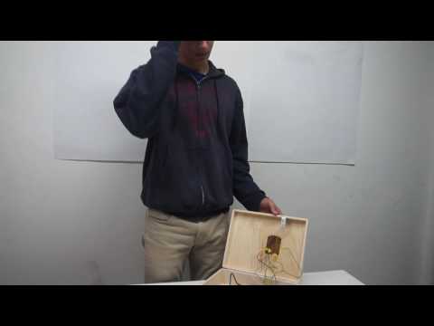
Getting the servo to lock and unlock with most of the parts wired and in place.
The lock on my box consists of one L bracket from the top of the box permanently in place. The servo motor turns and latches onto the L bracket, making the box unable to open. I attached the servo with a 3D printed clamp that held the servo in place. I ran into some small issues when making the lever that would hook onto the L bracket. The lever wasn’t long enough and allowed for too much of a gap in between the top and bottom parts of the box. Even when the box was locked, there was still room to reach your fingers in. I attached some scrap metal to the lever on the servo and taped on some small scraps of wood to thicken the lever and reduce the space in between the top and bottom. I also cut a hole in the top of the box where the 3x4 keypad would be. I attached the keypad and wired it to the Arduino.
Below is the mount for the servo. I 3D printed it, and then I attached this component to the side of my box and screwed in my servo. This was a very helpful component even though it was really small.

MILESTONE 1
Hooking up the Arduino to the keypad, making the Arduino read that the keys have been pressed, and printing them using the Arduino.
The wiring of this portion of my project was really easy; I just had to connect the different pins of the keypad to the digital pins on the Arduino. The only difficult part was to understand the circuit inside of the keypad. The makers set it up in an odd format making the pins connect with odd numbers and formations. In the beginning, I had to test which pins reacted to the push of each key. For example, when I touch the multimeter to pin 3 and 7 and then pressed 4, it beeped, indicating that the multimeter has detected a connection. When I touched pins 5 and 6, 9 beeped. With help, I understood the circuit. The test code that I downloaded for the keypad originally had some errors when I tested it. It would print weird numbers that would have little corresponding value with each other. I had to change around some numbers to make it sync up with my board. For the different rows I found the corresponding numbers. For row 1, the corresponding number was 2 (the sets were, 2,3=1 1,2=2 2,5=3). The corresponding number was 2 so for that row, the value would be 2. In the code, the value was set at a different number, so I had to change those for each row and column. It took me a long time to figure out what I had to do which set me back a little bit.
I made some changes because this schematic was based off of a 4x4 keypad, but I was using a 3x4. I took away the letters in the code and changed the number of pins to correspond to my project.
I used a different keypad but they both have 7 pins to attach to.

STARTER PROJECT
The starter project TV-B-Gone revolves around the microcontroller, reading signals and codes from the chip attached to the microcontroller. The chip is programmed with a set of about 130 sets of pulses that the different TV can read as an on/off switch. The microcontroller carries out the chip’s commands to the other components of the body. Those pulses will be transferred to the 4 transistors and then sent to the IR LEDs which will light up but cannot be seen by the human eye. The infrared receiver on the TV will read one correct pulse of light from the IR LEDs which will command the TV to turn on or off according to the state of the TV. This project wasn’t really that difficult to assemble and understand. After I finished the project and was going to test it, my green LED blew out and I had to replace that. Also, one of my IR LEDs either blew out or was just broken from the start. It took a long time to find out that was the problem because it could have been the capacitor behind it. With help, I now know that I can test the charge going through that component to understand where the problem is. We don’t have any other IR LEDs so I can’t replace it now. I learned that capacitors cannot change the amplitude of the currents but it can store energy. IR LEDs can be seen by digital cameras and other infrared sensors. TV remotes have set sequences of pulses for different commands of the TV. Finally, I learned how to check the voltage of different components.
Starter project video