Remote-Control Android App
The application will, with the help of an Arduino, remotely control a media device. Beyond that, it will allow the reprogramming of the controller as necessary, potentially saving the controls as a template for later use.
Engineer
Raymond W.
Area of Interest
Computer Science
School
Homestead High School
Grade
Incoming Senior
Reflection
Schematics, Arduino code, and MIT App Inventor package can be found in this GitHub repository.
Over the course of this project, I learned much about the two main communication protocols of the project. They happen to form two major challenges, as well. The first is with infrared communication. Actually, it is due to a failure to find manuals, and it busted one of the IR receivers. Once I rectified that, I discovered that the IR LED has trouble transmitting signal beyond a cone. I worked with this limitation, and just pointed the hardware toward the device’s receiver. Much of my problem with Bluetooth is with data transmission. Because of data delays between each send request, not all packages of data arrive when the programs detect presence of data. Thus, I must delay the process until all of it arrives.
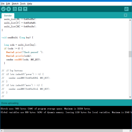
Aside from that, my attempt to map NEC codes to certain functions was bungled until toward the end. I thought I could have the programs send commands to each other, but without setting a delay, this caused programs to not work correctly. Most notable is the aforementioned data lag. Eventually, I simplified the process to the Arduino just listening to Android for commands, until it receives a code, after which it completes the mapping with a send request.
Communication is only half of the problem for the Arduino. Other issues have to do with Strings. Apparently String operations happen concurrently with program execution, and this causes problems when I want to use Strings almost immediately. Again, I have to set delays to keep the Arduino running correctly. All of that really speaks volumes about the difference between C and C++, which Arduino is written in, and Java, which I usually use. Fortunately, the syntax between the three languages are not too dissimilar, due to Java being an offshoot of C++.
Before this project, I had not considered working on three-dimensional design at all. Even when I did, I thought I would only need to make a simple box. As it turns out, the “simple box” was more complicated than I expected. I needed to work on the hinge-like devices and work around the 3D printer limitation, for example. 3D design in general is one of the most frustrating parts of my project.
I wrote too many lines of code to count. Memory is no object for an Android app, at least for small ones like mine. Memory, however, is precious for an Arduino. One of the last changes I made is to shift much of the code from the Arduino to Android. This makes future modifications easier, since the Arduino no longer has to store infrared codes in its memory.
Three years ago, I built a computer using parts procured from Fry’s Electronics. Now, I built an all-purpose remote control box with resistors, capacitors, and infrared components. Needless to say, I felt satisfied having done a hardware-building project.
Although functionally complete, the remote control is not what I consider available for public consumption. I will probably have to program in hundreds of lists, and that would take a while.
Final Milestone
The final milestone. After the remote control is operational, I started sketching the box that would contain the back end hardware, while also addition some features.
One key feature is the ability to set custom remote key mapping via controller input or manual input. For now, I will discuss controller input. Basically, by controller input I mean a controller inputs an NEC signal to the Arduino while it is in settings mode. To enter the settings mode, the phone must be connected to Bluetooth, and the phone must tell the Arduino that it wants to map a key binding.
A problem: how to handle Bluetooth connection during page change. I put a Bluetooth client to the main page and to the settings page, but the connection does not carry over. The workaround is disconnecting when I open the settings page, and then reconnecting. I did the same when I exit the settings page.
Another problem: how to stop the key setting. My first implementation has the setting button change name, and then loop until I receive information. The problem, however, is that pressing the same button causes the program to hang. I have to make use of Clock, which does something in an interval. As long as I start setting, the Clock runs and waits until it receives information. It then stores the information for loading.
To store the information, I used TinyDB, or at least MIT’s implementation of it. This component allows me to store data with a specific tag/key, and allows easy access to them with the same. When I store data, I only need to input a number and data (my back end uses numbers as commands) and TinyDB will store it for me. When I load data, I only need to specify a number for the component to load it, though I do need to set up a default. I can also clear data with it.
Implementing manual input setting is straightforward: a button that brings up a dialogue that inputs numbers. The dialogue accepts only decimal (0-9) and hexadecimal (0-F, where F = 15 dec), and the program stores it in decimal, though not before processing them as necessary.
On the main page, I have the program load data to the back end each time I connect via Bluetooth. I did the same when I go from the settings page to the main page. The data loading runs on Clock again, but this time I use TinyDB to load data from 0 to 38 on a 100-millisecond interval.
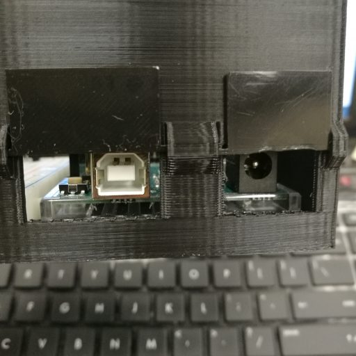
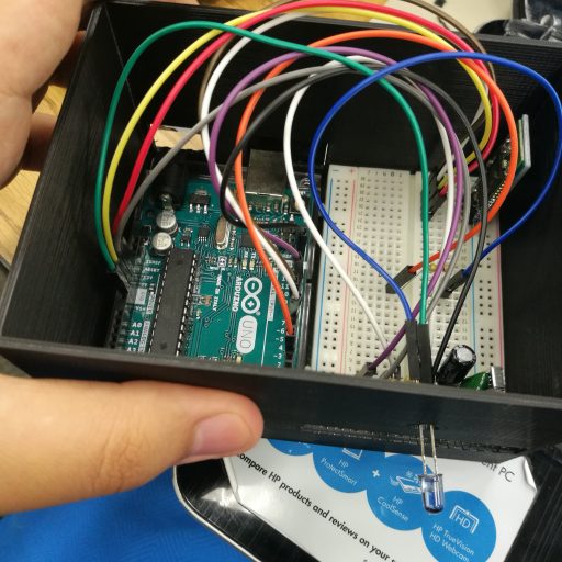
I have a somewhat harder time with designing. The Arduino Uno sketch I found on Tinkercad does not have a base that the back end one has, so I have to make one. Once I made the base and put the arduino and the breadboard together, I started making the case. Initially, I had the walls to be 5 millimeters thick. I also put a hole where the LED would pop out, and two more where the Arduino power portals are.
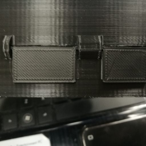
To cover the latter two holes, I used flaps. The flaps would have two poles sticking out, and they fit into sockets. Initially, the sockets would have a square side of 0.6mm each, and the poles 0.4mm each. I ran into a glaring limitation of 3D printing however. Specifically, the 3D printer will print at least 0.4mm x 0.1mm. I have to redesign the sketch to include larger sockets and eventually larger poles.
Some deformation still remains, but the flaps now largely cover the holes, and can move more or less freely. With all of that, most of the features and designs are now in place. That said, while the program does save custom settings, there is only a single copy. TinyDB, however, opens up an opportunity to create templates…
Link to the milestone back end build here. Link to the final version of the back end here.
Links to the milestone front end build here, and the final version here.
Second Milestone
For my second milestone, I mostly programmed in the back end – the microcontroller portion – of the project. I continued to use the same library – IRremote – because it also has functions that allows for the sending of IR signals. Initially, I used if/else if statements to have the arduino process the information received from Bluetooth and use it to send the correct signal through the IR LED. By default, and as of this writing, IRremote primarily uses Pin 3 for Arduino Uno.
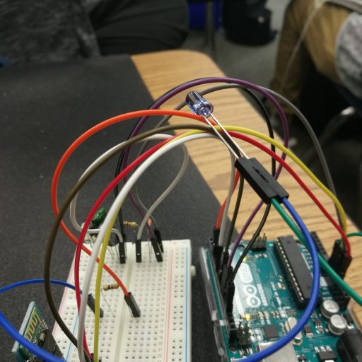
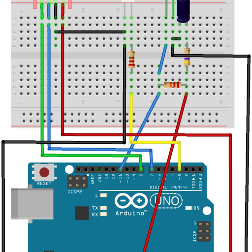
After programming them in, I attached the LED into the circuit with a resistor in series. When I first sent the signal from my app, it apparently does nothing. I then changed the bit of the signal from 3 to 32, and then tried to send it. Still nothing. Then I tried using 68, which still does nothing, and then back to 32. Each time, I moved the project close to the SMART projector. The fourth time, I aimed the LED up, and this time the projector turned on. I tested all the buttons, and only some did apparently nothing, if only it was not receiving signal from another device.
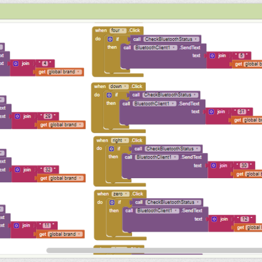
With that complete, I began working to implement buttons for my home television. I finished adding the missing 12 buttons into my app on the MIT App Inventor. At this point, adding buttons repeatedly has become something of a chore. I was adding more if/else statements when I grew tired of looking at a long piece of code that was full of if/else statements and little else. So I started looking for Arduino libraries that would reduce such a load for me. Someone suggested me that I should use arrays, but I dismissed him.
I eventually looked into StandardCPlusPlus, a library that tried to replicate the C++ base library as much as possible. Specifically, I want to use a map, which is a data collection type that stores values and associate them with keys. Initially, this was promising: I re-implemented the method to send SMART codes, and nothing changed much. But when I implemented fully 39 SEIKI codes, however, the arduino hangs.
An arduino contains a microcontroller, which performs operations. As it is small compared to a motherboard, it cannot hold as much information or compute as much as a computer could. The data has to be written into ROM – read-only memory – which is loaded when the arduino turns on. The cause of the hanging could be due to the imperfect implementation of the library or limitations placed on the microcontroller. In order to resolve the issue, I have to fall back on arrays. An array stores data and associates them with an index. Most other data types are arrays on steroids, like maps (arrays for keys and values).
In my case, each of the index represents a button, starting from 0 as the old “power” key. This meant changing the values in the Android front end, as well, which I did. When I reimplemented 39 functions into the back end, the arduino works as normal, no longer hanging in moments. Both the SMART and SEIKI functions work as normal.
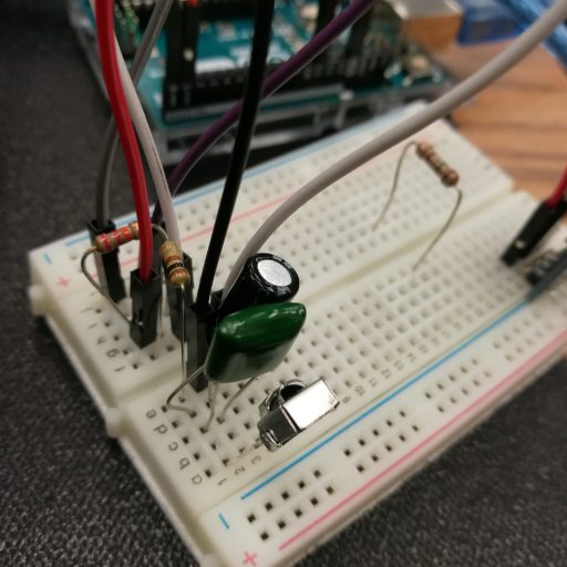
The transmitter, as it stands, is just a mishmash of wires and parts plugged into the arduino and the breadboard. I plan to conceal that with a box that can be powered by a power supply on the back, with an IR transmitter sticking out somewhere. This is only a preliminary design, and I plan to improve the design.
First Milestone
My project – the remote-control Android-Arduino hybrid – is based on the project linked here. This project uses much of the same materials and programs as the inspiration uses.
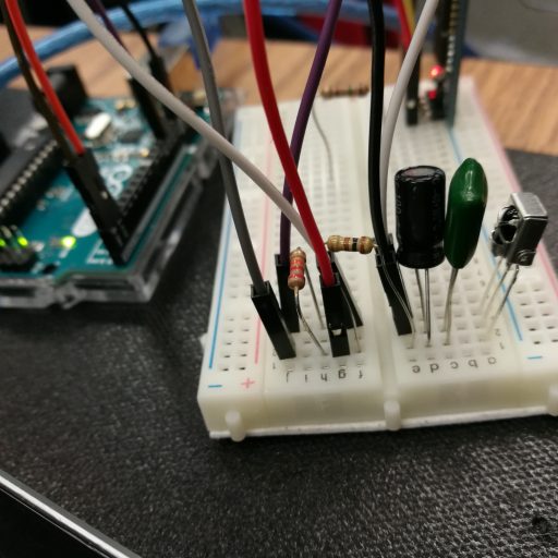
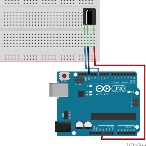
Completing my first milestone is interesting. To start off, I have to plug in an infrared receiver and complete its circuit blind, as in without way to know if I plugged in the parts rights. Consequently, I burned the first receiver, and did not rectify this mistake until too late. And I did not find out this until a mentor gives me a multimeter to measure the voltage drop across the receiver at the ground and voltage out pegs.
Once I got a new receiver and hooked it into the circuit, however, it started receiving IR signals from remotes and oddly from a smartphone. Only, most of the time the signal apparently has unknown encoding. It took me several tries just to get an NEC signal. To make them appear more often, I looked back at the receiver’s datasheet. I could understand Traditional Chinese, the language of the datasheet, a little.
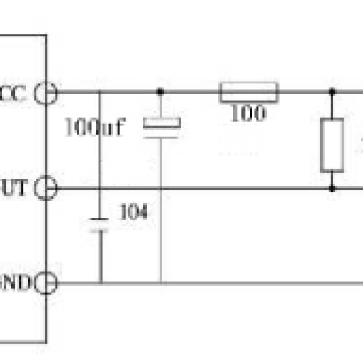
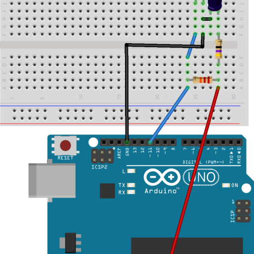
None of that matters, however, because I am looking at the application circuit, which appears to be a normal circuit. All except for the odd symbols for resistors (a narrow block) and electrolytic resistors (a block on the positive port). One of the capacitors uses code 104, which in a later search I found it to be 0.1 uF. I made a schematic using those information and procured those parts. The results are mixed, but much more consistent.
For this project, I used IRremote by Ken Shiriff. This library allows the sending and receiving of information through infrared. For now, I used the library’s example information dump to get the NEC code I need, which I record them in a spreadsheet. Later on, I plan to use the same library to send information of NEC encoding.
In the meantime, I have worked on the front end application for the project using the MIT App Inventor. The front end would send certain commands to the Bluetooth chip on the breadboard, which would then relay the information in the Arduino for processing. Then the Arduino would send an NEC signal to the IR LED for broadcasting. So far, the only function it does is checking Bluetooth status, as I have yet to program in the back end.
Starter Project
My Starter Project is the Big Time watch. The watch’s seven-segment display displays time when I press the side button. After a while, the display turns off, though I can press the button again to turn it off. While the display is on, holding the button changes the time. The time displacement increases as I hold the button for a longer time. Letting the screen turn off will confirm the changes.
The ATmega332 microcontroller processes information from the signal from the button, among others. Those include signal from the crystal, an electronic oscillator generating 32 kHz of frequency, used in clocks for time cycling. The microcontroller can be reprogrammed to show military time and other things, but AM/PM status requires making use of dots in the seven-segment display. The microcontroller requires a specific current and voltage, but the battery generates varying amounts of direct current. To smoothen the current and voltage flow, I used two capacitors: they absorb electricity when plentiful and release it when needed. To keep the circuit from short-circuiting, I included a resistor. Finally, the seven-segment display shows the current time, when on.
The two hardest parts of this project are soldering with a large head and assembling the shells of the watch. Several times, the soldering iron failed to solder due to me forgetting to heat the iron up. When they do, the unwieldiness of the iron makes precision soldering difficult. Later, due to the erratic placement of the button and the thickness of the button-handle, the third layer of the shell from the bottom plate appears to not fit into the frame when I place the handle. Fortunately, putting the screws into places resolves the issue, with the third layer being stretched to accommodate for the inclusion of the handle.
This project is a refreshing experience for me. Last school year I took Physics Honors, so I know much about circuits and resistance. However, the teacher covered less on capacitors and none on oscillators. With this project, I am able to learn more about the electronic components in a circuit board and their uses.


