Real-Time Planet Tracking System & Trajectory Prediction
The Real-Time Planet Tracking & Trajectory Prediction System (RTPT) tracks celestial bodies using Kepler’s algorithm. The RTPT is programmed through Arduino and takes the orientation and location of the system.
Engineer
Priya R.
Area of Interest
Computer Science
School
Dougherty Valley High School
Grade
Incoming Senior
Final Milestone
Second Milestone
First Milestone
MPU can calculate motion parameters such as Linear acceleration, Angular acceleration, and the Magnetic North of the planet with a reference point on the object. MPU9250 has an accelerometer, gyroscope, and a magnetometer. The MPU has raw readings of the Euler’s angles the three angles : yaw, pitch, and roll. It measures the orientation of the object. The MPU stores the data from the sensors and the data is transmitted over I2C Serially.
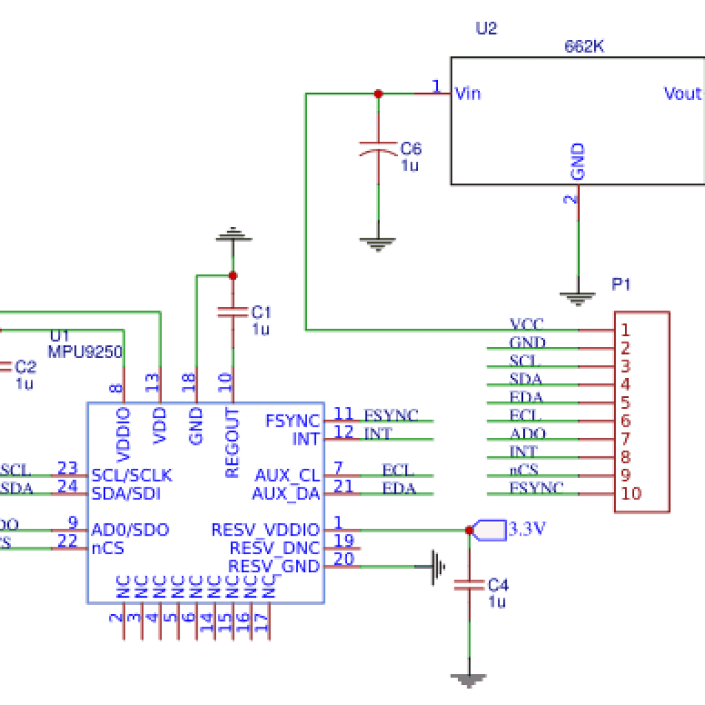
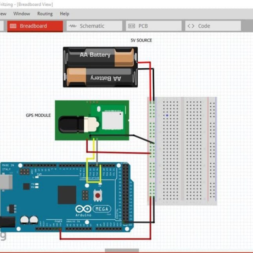
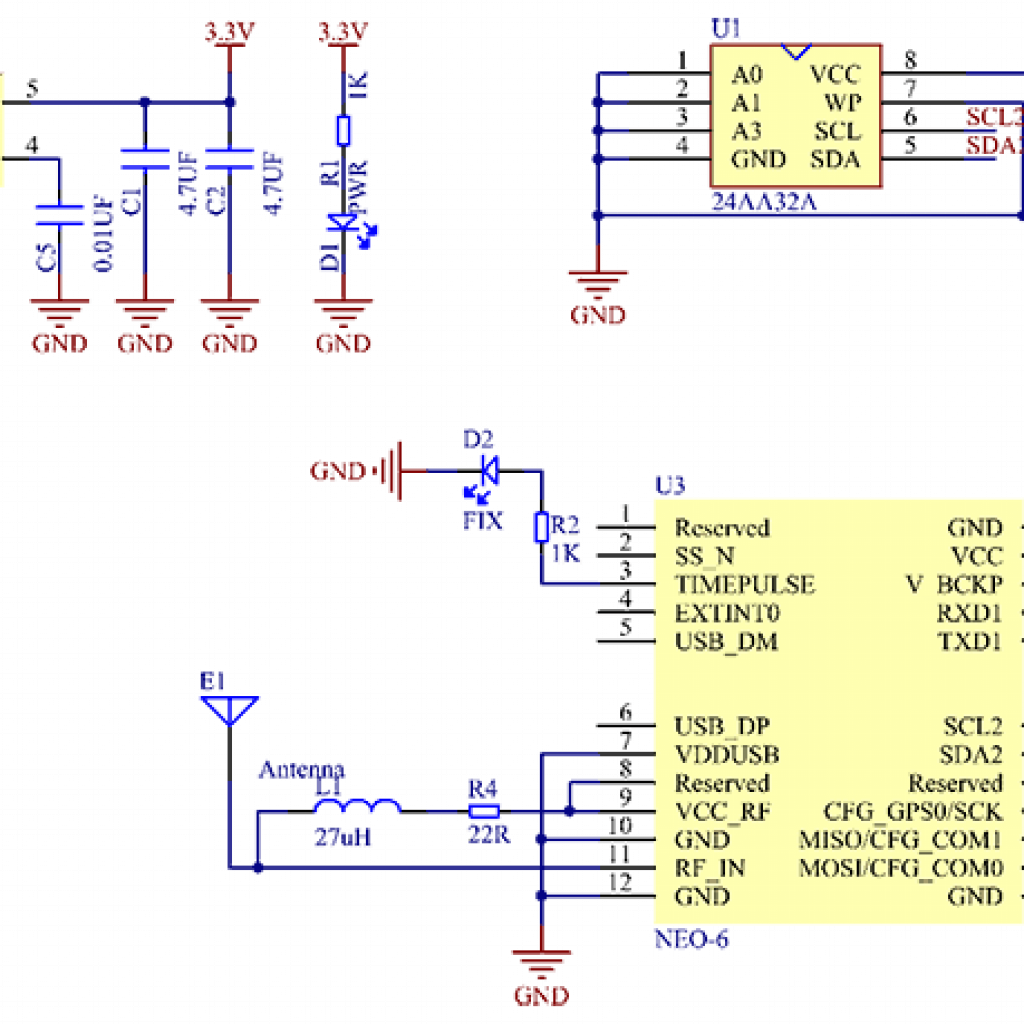
The GPS receiver provides the values of the latitude, longitude, date, & time. The biggest challenge with the GPS is the readings, which are inconsistent and works the best outdoors. The signals from the satellite , travelling at the speed of light, are intercepted by the GPS receiver
The potentiometer uses the analog pin and forms a range of 0 to 1023, which is proportional to the amount of voltage being applied to the pin. Turning the potentiometer acts like a switch, as dependent on where one turns the potentiometer, the RTPT will show a different planet.

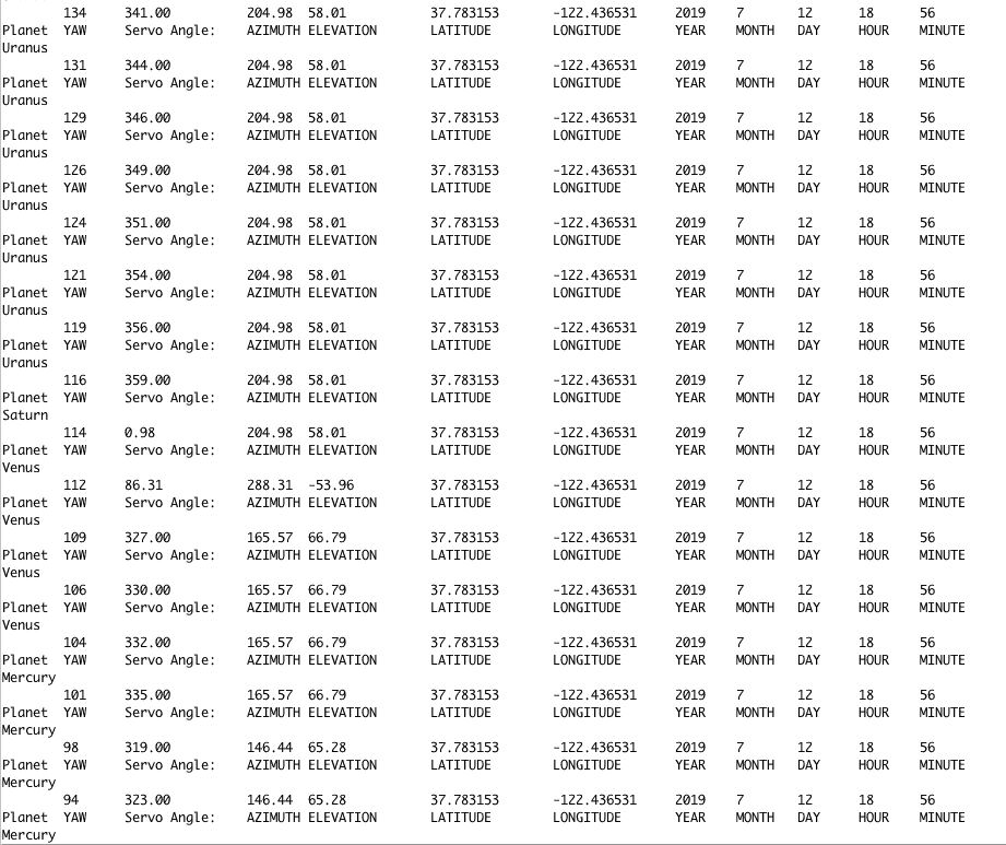
The servos allow the laser to point to the correct angle. The servos angles are dependent on the Azimuth-Altitude calculations derived through Kepler’s law. These calculations are used through the time and date.

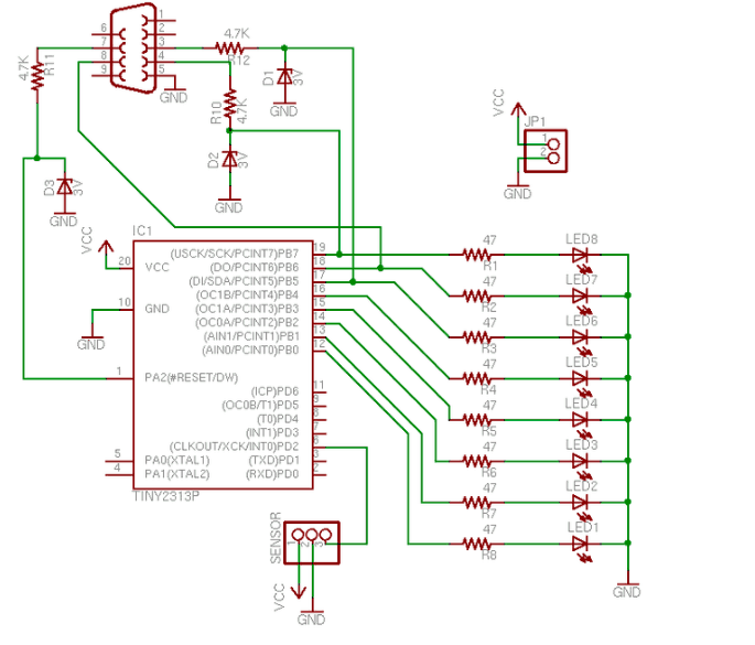
MINI POV
My starter project was a mini POV (persistence of vision) programmed by a microcontroller. Powered by two AA batteries, the POV is programmed so if one shakes it fast enough, the viewer can read the pattern created by the LED lights. Starting off the project, I soldered around the connection of the board and the resistors. The resistors, which were 4.7K and 47 Ω, were not directional; the zener diodes, however, were directional. After placing the resistors, LED bulbs, zener diodes, and serial port connector, I connected the serial/usb convertor to a PC to install the software for the POV. To install the software, I first setup the firmware and customized the pattern of the POV. I changed the delay time of the POV using wordpad to make it easier to display the pattern created.