
IoT Weather Display
The IoT Weather Display is a customizable weather forecast device that exhibits different colors, each representing a specific weather condition, by retrieving weather data from any location in the world.
Engineer
Orly S.
Area of Interest
Electrical Engineering
School
SAR High School
Grade
Incoming Junior
Final Milestone
For my First Milestone, I accomplished changing the color of the NeoPixel Ring manually, and for my Second Milestone, I directly connected the Dark Sky weather data platform to my Particle Photon, to retrieve current weather conditions and send the information to the NeoPixel Ring, which translates the type of weather condition to the color it is paired with in my code.
For my Final Milestone, I focused on the hardware and aesthetics aspect of the IoT Weather Display. I took my clear plastic jar and filled it halfway with cotton balls, embedded the NeoPixel Ring, and added more cotton balls until the jar was full. Next, I needed to construct a lid. Originally, I planned on 3D printing a lid, but I brainstormed other ways of creating this specific lid to save time and money, and decided to use a wipe container lid to be more resourceful. This was a little big for my jar, but it had a perfect, “built-in” opening that my USB cord could fit through.
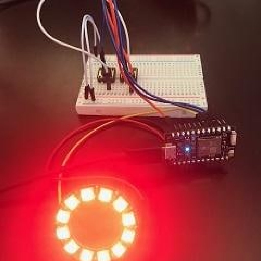
Following this, I decided to transfer my circuitry to a perfboard using jumper wires, instead of a breadboard using male-to-male and male-to-female wires (a challenge!). A perfboard works better for my project because it enables more permanency and the electrical wiring cannot become loose. After a lot of time and patience, I deconstructed my original circuitry and reconstructed it on a perfboard. I soldered in solid core wires and hot glued everything to make it “more” permanent. After the hot glue cooled down, I velcro-ed the board underneath the lid. This marks the completion of my IoT Weather Display, as my code, circuitry and hardware are all aligned!
Second Milestone
For my Second Milestone, I focused on retrieving current weather conditions and automatically displaying the color associated with the condition on the NeoPixel Ring. I used the Dark Sky platform, which gathers weather data, and its API, a set of functions that creates an application using another source, allows you to retrieve weather data from anywhere in the world. I began by creating a Dark Sky account and an API key. In order to extract current weather data, I needed to create a URL in Particle’s integrations feature that would include my API key, and the latitude and longitude of the location of my choice. Because I live in New York, I first used New York as a location. When I ran the code, Dark Sky transfers the current weather in New York to my Particle Photon, which is connected to the NeoPixel Ring. In my code, I linked types of weather conditions with specific colors, and the Ring translates the weather information into the color it is paired with.
There were a number of challenges that I faced over the course of this milestone. My first problem was that originally, I planned on using the Weather Underground platform on IFTTT, but I learned that it would not accomplish what I would want, so I then needed to switch to the Dark Sky platform. This challenged me to understand a new code and a new mechanism, but after some time, I adjusted. Additionally, as soon as I got Dark Sky to run, it gave me future weather conditions, and not real-time ones. Finally, I figured out the problem, which was that I left out the key word “api” in my URL. Something else that confused me was that certain weather conditions were tied to the same color, so I quickly undid this by adding more color options to my code. Ultimately, although this proved to be a challenging Milestone, when everything “clicked,” I gained a sense of fulfillment and accomplishment!
First Milestone
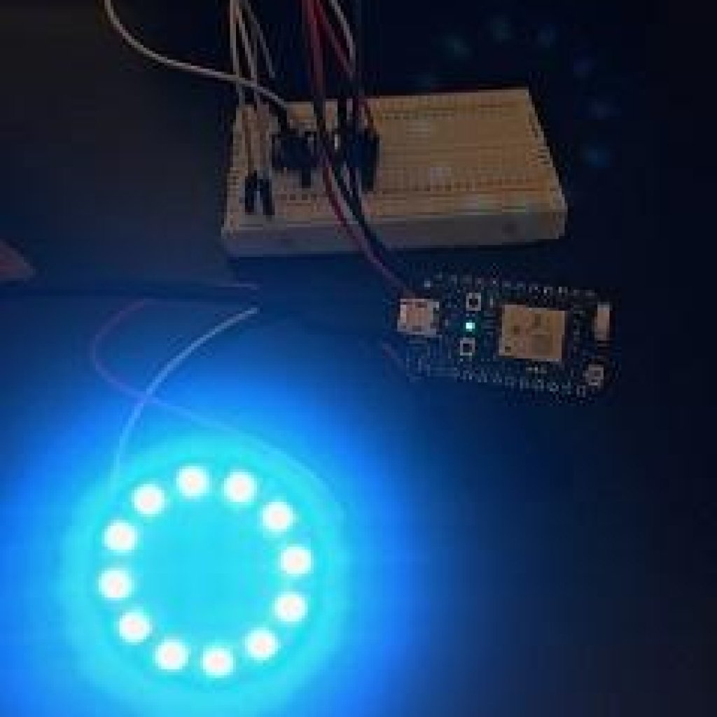
My First Milestone was to connect the Particle Photon to WiFi and use it to make the NeoPixel Ring light up its LEDs. The Particle Photon contains a microcontroller and a Cyprus WiFi chip. Following the directions on the Particle website, and after multiple attempts, I finally connected my Particle Photon to WiFi, which is important because it allows it to take information from the Cloud. The power travels from the computer, which connects to the USB port of the Particle Photon, which is connected to the NeoPixel Ring directly and momentary switches through a breadboard. The way in which the NeoPixel Ring works is that each of its twelve pixels contains three LEDs, with the colors blue, green and red. You can control the colors each pixel displays by regulating the level of brightness of each LED.
Furthermore, on the breadboard, there are three different connections. The first is connected to the V-IN, which supplies power, and that wire is connected to the Power Receiver on the NeoPixel Ring, which, as it sounds, receives power to light up the LEDs. The second is controlled by the buttons. It is connected to the 3.3V pin on the photon, which supplies power. And the buttons are connected to the D3 and D2 pins on the Particle Photon, respectively. The first button is responsible for changing the colors, and accelerating the sequence. If you picture it, when the button is pressed, it connects the 2 sides of the button, leveling out the ground, and connecting the button to HIGH. In my code, I wrote that when the button is pressed, the numbers associated with each weather condition will increment; thus changing the color. The second button is responsible for bringing the weather conditions to square one. In my code, I wrote that when the button is pressed, and thus connected to HIGH, the sequence is reset to the first weather condition. The third connection starts at the D4 pin on the Particle Photon and is connected to the Data IN on the NeoPixel ring.
Before officially wiring each circuit, I decided to begin the code. Using the IoT Weather Display tutorial, I pasted the code given into my personal Particle app. After familiarizing myself with the code, I completed wiring the circuit. Instead of connecting the NeoPixel Ring to the Particle Photon via breadboard, I soldered in male-to-female wires connecting the Power Receiver on the NeoPixel Ring to the VIN pin on the Particle Photon, the GND pin on the Ring to the GND pin on the Photon and the Data-IN pin on the Ring to the D4 pin on the Photon. All in all, this gives the NeoPixel Ring the power to light up the LEDs according to the information given to it by the Particle Photon. I then connected two momentary switches to the D2 and D3 pins and then to 3.3V pin. When I was confident in the accuracy of my wiring, I had the code and the wiring run in unison, and everything worked as instructed.
Some of the challenges I faced included difficulty with the buttons. Originally, they did not work, so after obsessively checking the accuracy of my code and wiring, I decided to switch the buttons out for new ones. Although this initially seems to be a minor change, it actually was the root of the issue, because after replacing the buttons, the buttons worked correctly. Another issue I faced was having to redo the code, as I switched platforms in the middle. Instead of using Weather Underground, which was faulty because it only displayed color when there was a change in weather, I switched to Dark Sky as a solution. This was challenging because it meant understanding a new code and new platform.
Starter Project
Demonstration
For my Starter Project, I decided to construct the MintyBoost, a portable charger for your device powered by two AA batteries. I began by soldering each piece; these included resistors, capacitors, and most importantly a boost converter chip, a power inductor and a diode. The power begins at the batteries, travels to the inductor, and when the boost converter flips the switch open, the power will travel through the diode to the USB port, through the cable, and the phone!
It was not too challenging to build the MintyBoost; as soon as I acquainted myself with soldering, it became less time-consuming and more efficient. After I completed soldering, I needed to fully familiarize myself with each part, in order to interpret the connection and relationships between each component. The MintyBoost enabled me to perfect my soldering skills, get accustomed to the BlueStamp work environment, and gain a sense of accomplishment after independently creating a functional portable charger.
How it works
The MintyBoost is powered by two AA batteries, each 1.5 volts. There are five resistors, which limit the flow of electrons through a circuit; they ensure that the charge produced will not overwhelm the device. There are also four capacitors, which work together to secure an output of 5 volts. Two ceramic capacitors stabilize the current when a change in voltage occurs and two electrolytic capacitors store energy. The most important features of the MintyBoost include the boost converter chip, the power inductor and the diode.The boost converter chip is responsible for converting input voltage into output voltage. In our case, the boost converter chip, with the help of the power inductor and diode, increases the 3 volts from the batteries to the 5 volts necessary to charge the device. Note that the boost converter chip sits on the IC socket, which protects the chip and enables the user to easily remove it.
In terms of power, energy begins at the two AA batteries and it travels to the power inductor, a coiled wire in which electric current flows. The boost converter chip has the power to flip the switch from open to closed. When the switch is closed, the inductor stores energy in the magnetic field formed by the electron flow. However, when the switch is open, current is reduced as resistance increases, which in turn destroys the magnetic field and converts it into a boost of voltage. This charges the capacitors, thus stabilizing the voltage in the boost converter chip. The boost converter then creates an alternate circuit pathway, lowering the current in the inductor. In response, the inductor creates a weaker, opposing current. Due to its weak current, it has a high voltage, which is expressed through the law P=IV. This current flows through the diode, which is responsible for transferring energy directly to the USB port and barring any energy from going in the opposite direction.
MintyBoost Schematic
