CNC Plotter
I am creating a CNC Plotter for my main project. A CNC Plotter is a computer controlled drawing machine that uses g-code files which contain position coordinates to accurately draw.
Engineer
Nikhil P.
Area of Interest
Electrical Engineering and Computer Science
School
Los Gatos High School
Grade
Incoming Senior

Reflection
When I started Bluestamp I had very little experience with engineering. This program made me have to be very independent in creating my project and at first, I was not that independent. I have never done a program or class where I had to go at my own pace so at the beginning I wanted confirmation that I was doing everything right. I realized that I needed to trust my own judgment because I am usually right and if I am unsure about a problem that I can find the answer by myself. One of the problems was when my CNC Plotter would lose its position when drawing. After doing a lot of research I found the problem was that my code called this command called microstep. Microstep caused my stepper motors to lose torque so if my motors had to move a very small amount they wouldn’t move at all. I found this other command called interleave which got rid of the problem and allowed the plotter to work properly. This was my favorite memory from this program because I worked for a long time on this problem and tried many potential solutions to no avail, so I felt very accomplished when it started printing properly. This project has made me realize that I love engineering and would like to major in electrical or mechanical engineering in college.

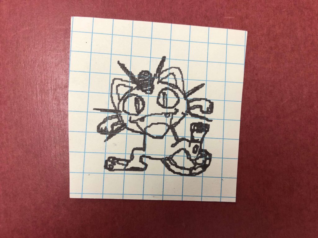
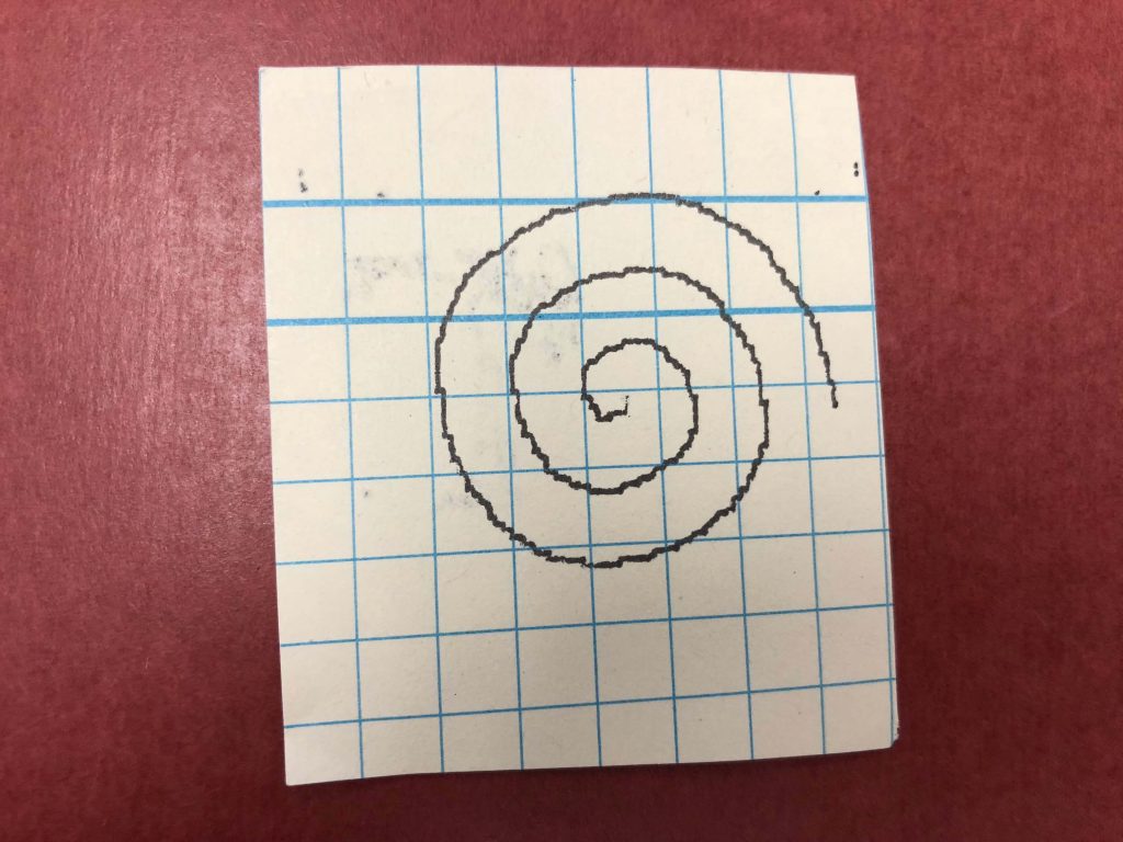
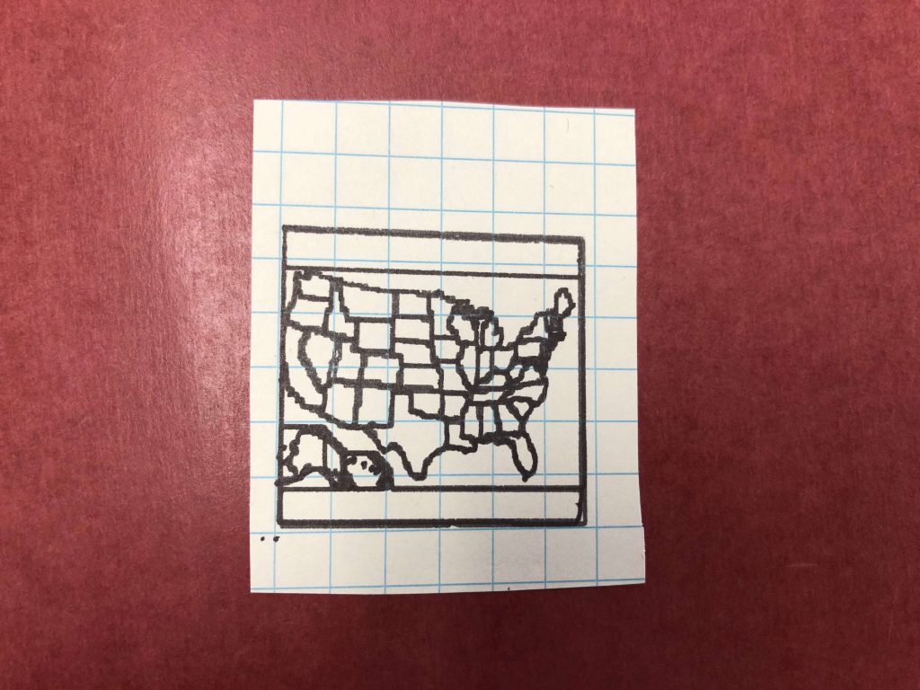
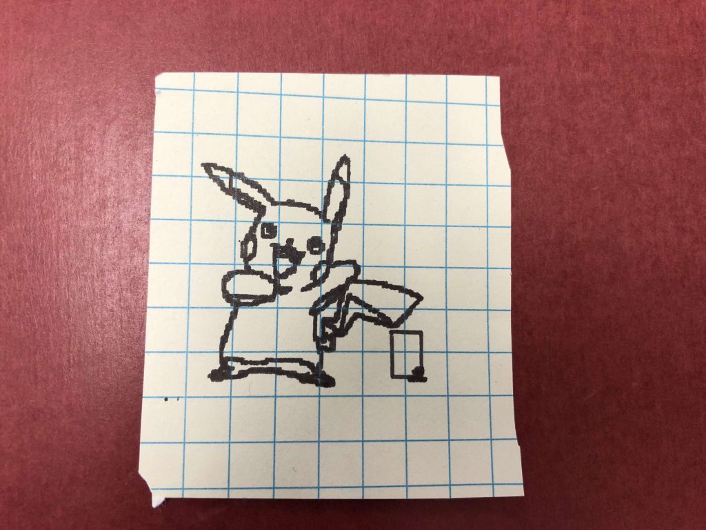
For my final milestone I setup the z-axis and got it to print my own g-code. I used this slider piece from my CD drives so that the pen can move up and down. I used a servo motor which is connected to fishing wire that is connected to the slider piece to control the z-axis. I used fishing wire because the servo could not be directly attached to the slider since the servo has to move freely. When I started working on the code I had to change the commands that called the stepper motors since it was coded for an Arduino that was not using an adafruit motor driver shield. I found some gcode online to test the plotter and realized that there was a problem with the stepper motors. I noticed that there was some type of resistance that caused the motors to not move properly because the drawing would start off fine and then the further along it got the worse the drawing got. After doing some research I realized that there was a problem with using microstep to move the motors in the code. Microstep causes the motors to lose torque causing it to not work properly. I changed the code to use interleave instead of microstep which fixed the torque issue. The next step was creating my own gcode files. I use a program called Inkscape which can save an image as gcode. I was then able to upload my own images.


For my second milestone, I built the structure for my CNC plotter. I hot glued my two stepper motors to the acrylic platforms. I then mounted both platforms perpendicular to each other to create the x-axis and y-axis. I put L brackets on the y-axis to add support to the structure, but I could not drill the L bracket on the x-axis because the hole would be too close to the edge of the acrylic, so I had to hot glue the pieces together. I then created a temporary drawing platform with tape and cardboard and a pen holder with an L bracket and tape. I also wrote some basic code to move the stepper motors to draw a square. When creating this structure I had a problem with mounting the CD drives to the acrylic since I didn’t want the screws to go all the way through the acrylic. To solve this issue I had to drill a small hole and then file the acrylic at an angle. I also used hot glue to secure the CD drives and make sure that they were level. My next milestone will be setting up my servo motor to move the pen on and off the paper. I will also create a permanent drawing platform out of wood or acrylic. After that, I will be able to write the code to draw a gcode file.


