Hi, my name is Netanel. I am a rising Junior at SAR High School. My starter project was the Mintyboost Portable Charger, and my main project was a Gesture-controlled Robot with a Robotic Arm. I chose this project because I wanted to challenge myself in a unique way and try something that would greatly expand my knowledge in engineering.
My experience at BlueStamp has not only taught me more about engineering, but also taught me lessons for life in general. When I built projects before I came to BlueStamp, I would put the parts together, just as the instructions instructed me to do. I was putting pieces together, but I did not understand how or why they worked. BlueStamp has taught me to understand why certain components are included and what each component does. By understanding what I am working with, I don’t need to ask other people questions about why my robot is not working. Instead, I can figure it out by myself. Through my experience at BlueStamp, I learned to rely less on other people’s help and to try to solve my problems by myself.
After completing BlueStamp, I now see myself as an engineer, and I look forward to using my newly possessed skills in the near future. This experience has further pushed my interest in engineering. I now know that I would like to pursue engineering as a profession.


Final Project:
Final Project Video:
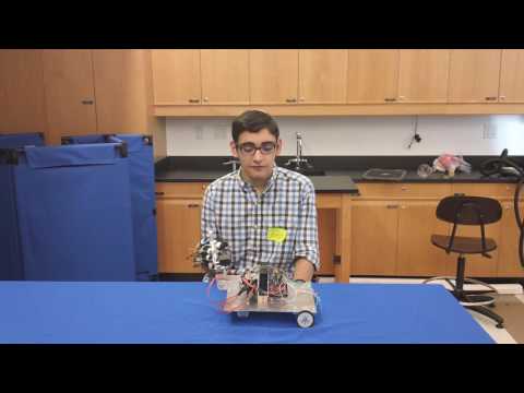
The most challenging thing I faced while doing this project was that my 12 volt battery was not powering everything on the car like it was supposed to do. It took me a couple of days to actually figure out what the problem was. I had originally thought that maybe some of my wires were not actually connected, but I discovered that this was not the problem by checking each connection. I eventually figured out that the problem was that the battery supplied not enough current for all the components. I discovered this by disconnecting some of the components from the battery. When I did that, the connected components worked perfectly. I solved this problem by attaching a second battery to the car. There is now one battery powering the Arduino board and the DC motors, and another battery controlling the servos in the robotic arm. The most challenging part of this problem was not solving it, but rather finding out what the problem was.
Schematics:
Schematic for the Glove:

Schematic for the Car and Robotic Arm:

CAD for DC Motor Mounts:

Code:
Bill of Materials:
Second Milestone:
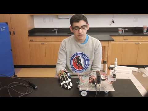
My second milestone was getting the servos and DC motors to respond wirelessly to the flex sensors. To accomplish this, I had to use XBees. I configured the XBees by assigning them the same PAN ID. PAN ID stands for personal area network, and if two XBees have different PAN ID’s, they will not communicate with each other. I attached an XBee shield to each of the Arduino boards, which allowed the Arduinos to communicate wirelessly over radio waves. The XBee on the glove would send a character to the XBee on the car depending on which flex sensors were bent. The XBee on the car would then receive these characters, and depending on which character it received, the Arduino would perform a different action. To control the DC motors, I had to use an H-bridge. An H-bridge is a series of switches, controlled electrically, that when opened or closed, allow voltage to go to the motors.
Second Milestone Video:
First Milestone:
My first milestone was getting a claw to move depending on how much a flex sensor was bent. The first thing I had to do was to find out what numbers the flex sensors would send to the computer depending on the resistance caused by the bent flex sensor. The more a flex sensor is bent, the higher the resistance the flex sensor produces. I then changed that output to come out as numbers between 0 and 180 instead of the original output. so I programmed an Arduino, a micro controller, to tell the servo, a motor that can only rotate 180 degrees, turn to the degree that the flex sensor was now outputting.
First Milestone Video:
First Milestone Schematics:
Starter Project:
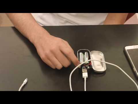
For my starter project I built a Mintyboost Portable Charger. The charger runs off 2 double A batteries. The double A batteries release 3v to the inductor and the inductor stored the current as magnetic energy. The IC chip closes a bridge, and because of the inductors physical properties, it will turn magnetic energy into electrical energy to counter any change of energy. The current then travels to a diode, which allows the current to only travel in one direction. This way the charge will only travel to the USB port, and won’t travel back towards the battery. This IC chip continues to open and close the switch, gaining a small amount of energy each time until there is a steady 5v that will leave the inductor. The current then travels through a series of resistors and capacitors which stabilize the voltage and let a smooth flow of electrons to travel to the USB port. The energy then travels to the USB port and charges your phone.
Starter Project Video: