
RC Robot Tank
The RC Robot Tank is a robot tank controlled by a PS2 game controller that can move in all directions. The tank receives code from an Arduino which is a type of microcontroller, or computer. It consists of a PS2 controller, gearbox, Arduino, L298N motor driver, chassis, wheels, and tank treads.
Engineer
Matthew F.
Area of Interest
Civil Engineering
School
Garden City High School
Grade
Rising Junior
Reflection
As a second-year BlueStamp student, I refined the skills I learned last summer in electrical engineering, and learned all about mechanical engineering and coding. Coming into the program this year with nearly no knowledge of coding, I am now leaving with a fully functioning robot and have gained an interest in the field. BlueStamp has set me up for success in the future; having two years of hands-on experience allows me to accurately decide what fields of engineering I would like to focus on in the future.
Final Milestone
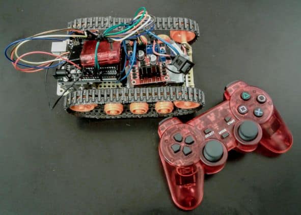
For my second milestone, I added the PS2 controller to my RC Robot Tank so that it can be controlled wirelessly. I can now click different buttons on the controller and the tank will immediately complete the command assigned to the button pressed. Currently, the direction buttons make the tank move in that specific direction. For example, if I press the right button on the PS2 controller, the tank will turn right. Additionally, the triangle button on the other side of the controller stops the tank completely. In order to make all of this happen, I first wired the Bluetooth PS2 receiver to the Arduino’s input pins so that any commands the receiver is sent, the robot tank will immediately follow. I then downloaded PS2x code from the Arduino library. From there, I customized this code to assign each button on the controller a different function. Now, when I turn on the controller and the tank, I can press any button on the controller and the tank will immediately move. Now that I am finished with my base project, I would like to add lights and a buzzer as modifications in the time that remains.
First Milestone
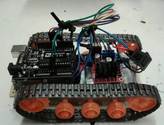
For my first milestone, I fully assembled my RC Robot Tank and edited preexisting code in order for it to move. Though my tank currently moves back and forth in a straight line, it will eventually move in all directions and receive information via a PS2 game controller. To start, I assembled the gear box, which allows the motors to rotate one wheel on each side of the tank. By spinning one wheel, the rest of the wheels move as well since they are connected by the tank treads. After doing so, I attached all wheels and the gearbox to a chassis, or base for the project. Once everything was assembled, I began wiring my Arduino Uno to be ready for the code to make the tank move. An Arduino is a microcontroller which serves as a computer by telling the tank what it needs to do. Currently, the code from my computer is sent to the Arduino and then to Motor Driver L298N, which amplifies the current from the battery. The motor driver allows the motors to receive more power in order to more easily move the gears in the gearbox, therefore making the wheels spin more effectively. Additionally, the h-bridge within the motor driver allows the motors to spin both forwards and backwards. Once I finished setting up these parts and assembled everything to the chassis, I downloaded code from the Arduino library that is specific to the motor driver I am using. I then edited the code so that both of my DC motors would spin, rather than the one that the original code was meant for. Additionally, I reduced the speed at which the motors spin at. Unfortunately, one of my motors will not move at a speed lower than 128 so my tank has to move pretty fast. However, the tank is assembled and moves using the proper code. I now plan on connecting the PS2 controller to direct the tank wirelessly. After that, I would like to edit the code to allow the tank to move in more ways by using different controls on the game remote.
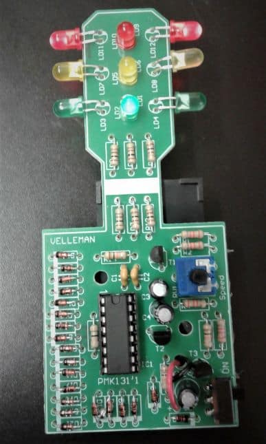
Starter Project
For my second year starter project, I built the traffic light by Velleman. By flipping the switch on, the traffic light illuminates and cycles through colors, from red to green to yellow and back to red again. The colors change as any four-way traffic light would, allowing traffic to pass through any given intersection. The speed in which the lights change can be changed by the knob on the trimmer. In order to work, the switch is turned on; this completes the circuit. In other words, electricity from the battery is able to flow through the circuit board when the switch is flipped on. The first place the electricity flows to is the integrated circuit (IC) which is simply a pre-programmed computer that tells the traffic light how to function. As it contains an oscillator, the IC controls the timing in which the LEDs light up. From the IC, the current flows through a series of resistors and transistors which ensure that the proper amount of electricity is flowing through the circuit board. Resistors are only capable of slowing down the current, while transistors can slow down or speed up the current. In addition, the current flows through twenty-one diodes in order to prevent the backflow of electricity. In addition, the current flows through a few capacitors which store and release electricity to stabilize the voltage of the system. Finally, the current reaches the LEDs, or light-emitting diodes, which give off the light that makes the traffic light work. From making this project, I was reminded that LEDs can only be soldered to a circuit board in a certain way. The longer leads have to be soldered into the positive hole in order for the LEDs to light up. Unfortunately, I did not read the directions properly and put all of the LEDs in the wrong way at first, resulting in me having to desolder all twelve of them. Though this took time, I will always double check which way to solder diodes before doing so in the future. I look forward to starting my main project, the RC Robot Tank, very soon.