3D Printed Prosthetic Hand
Hello!
I’m Matthew W and I’m a rising junior at Glen Ridge High School, and I’m also a second year student here at Blue Stamp! For my starter project this year I created a MintyBoost portable charger and for my final intensive project I built a 3D printed prosthetic hand (shown on the right) based off this instructable.
Engineer
Matthew W.
Area of Interest
Environmental Engineer
School
Glen Ridge High School
Grade
Incoming Junior
Reflection
In my second year at Bluestamp, I decided to return to the program to further challenge myself with a more lengthy and intricate project. This is why I decided to construct a 3D printed, prosthetic arm as my main intensive project. After completing the build of my servo powered hand, I am left with a product that serves the purpose for fun gestures and educational value about engineering. Thanks to the instructors and my fellow students for pushing me to limits I could never achieve alone!
Final Milestone
Code
Materials
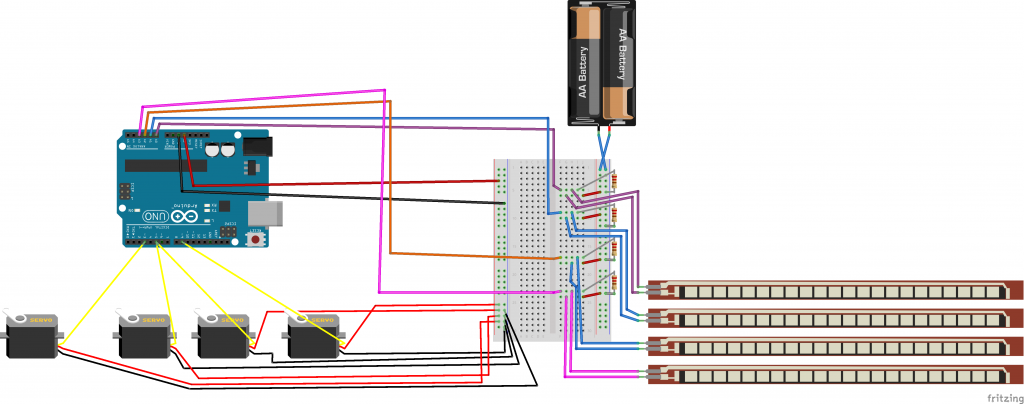
Schematic
This is my second year recap! Thanks for a great second year Bluestamp!
Second Milestone

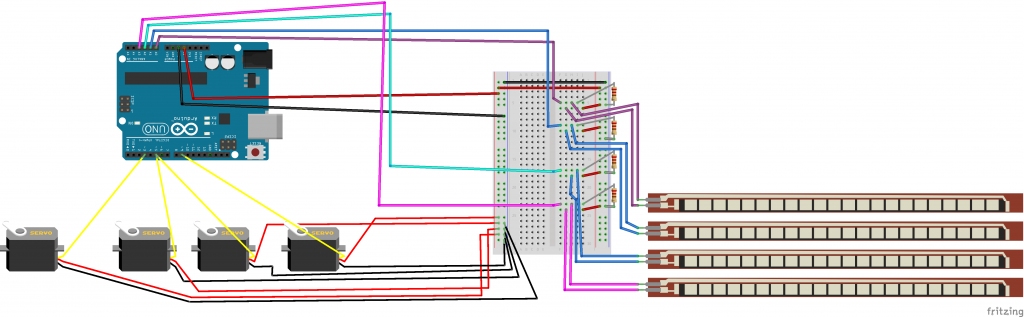
Figure 1: A Fritzing diagram of my new circuit can be seen above
First Milestone
