Third Eye For The Blind
Being known as the first wearable technology for the visually impaired, I will be recreating & adding my personal touch to my project. The Third Eye for the Blind helps the visually impaired guide themselves without the need of depending on another person, service dog, cane, etc… Giving the user more independence and confidence.
Engineer/Bio-Technician
Marvin V.
Area of Interest
Mechanical Engineering, Entrepreneurship, Bio-Tech
School
Summit Preparatory Charter High School
Grade
Incoming Junior
Final Milestone
Furthermore, I noticed some faults in the original project, therefore I set out to make my own modifications. I first decided to create a case that is aesthetically pleasing. I also tried to perceive a more functional model by adding another ultrasonic sensor.
I noticed that in the original project the user had to extend out their hand to guide themselves, therefore I thought it would be more beneficial if I moved the module to the wrist and added another ultrasonic sensor. The reason behind adding another ultrasonic sensor to the original module was to widen the range from 180 degrees to 270 degrees, thus the user can walk normally without extending their hand.

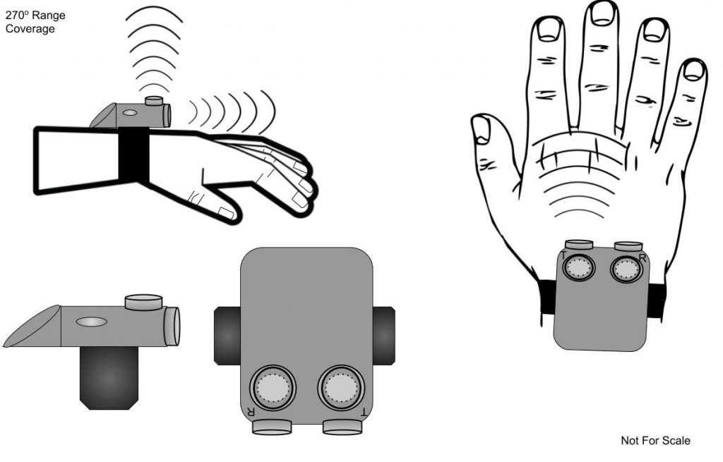
I also tried to take in hand human bipedalism, this goes unnoticed but I tried incorporating it in my project, so that I could have the most efficient module. I did extensive background research regarding human bipedalism, and the angle of motion of the users hand when they are walking. I found out that humans naturally sway theirs arms in an opposing direction with respect to the lower limb, which reduces the angular momentum of the body, balancing the rotational motion produced during walking. Also that humans naturally sway their arms in a 75-90 degree motion in a straightforward manner. Thus I came with the conclusion that if I added two ultrasonic sensors in a 90 degree manner, I could in turn have a 270 degree range rather than a 180 degree range. This would in turn benefit the consumer by not only by not constricting the hand but also by having a wider effect of range.
Third Milestone

For my third milestone I decided to add an elastic band. In the original project guide the elastic band and ultrasonic sensor are on the palm, thus constricting and objectively making it uncomfortable for the user. I then decided it would be best if I configured my biomedical device on the wrist, thus not constraining the user’s hand and at end makes the device more comfortable. Relocating my device to the carpal bones (wrist) also provided additional protection, since my device is meant to be worn on the non-dominant hand. Resulting in less movement/activity and less wear on the instrument.


Second Milestone
For my second milestone I was able to solder all my leading components to have a fully functional product. To get to my second milestone I had to revise my previous work so that it could properly fit and make sense when translating my work into my printed circuit board. I redid my circuitry on my breadboard because all my wires were unorganized and I wanted my breadboard to be as clean as possible. I ended up using a different type of jumper wire so that I could easily identify where all my components were placed. I then started working towards creating a schematic. Since my parts are limited as well as time, I thought it would be best to plan out the actual circuit.

How does this all work? My schematic consist of the following components, (stated in my schematic). My photon board(arduino pro-micro) is one of the primary components, my arduino board consists of both a physical programmable circuit board (often referred to as a microcontroller) and a piece of software, or IDE (Integrated Development Environment) that runs on my computer, used to write and upload computer code to the physical board. The actual code that is ran by arduino is C++, commonly known as a collection of predefined classes, which are data types that can be instantiated multiple times. Therefore specific commands you program and upload on the arduino board are then executed by the microcontroller with both digital and analog pins.
Finally, some obstacles I overcame include having to resolder everything on to a new PCB since my previous board didn’t work. Since the soldering was really messy on my PCB I thought it would be best to restart and make it better, I didn’t want to settle for less. Afterwards I had to find what else was wrong with my circuit, in my previous PCB my switch didn’t work as it should have. The switch only turned my LED on and off. Therefore I went over my circuit and found that I didn’t properly solder my ultrasonic sensor.
First Milestone
Today, I hit my first milestone, which was getting one of my components to properly work with my ultrasonic sensors. I came to this by understanding the code that was provided and wiring the LED accordingly. First, I went over the code that was provided and went through the arduino language reference so that I could have the best acknowledgement regarding what the specific code did and how it worked. Regarding wiring and how I got my LED to function I first wired my 5v & Ground (GND)(which are pins from my arduino board) to the power column in my bread board. I then, wired my ultrasonic sensors to my arduino board. Specifically I connected my VCC (Voltage at the Common Connector +) and GND (Ground -) to the power column in my bread board. I then connected my Trig & Echo to pin 12 and 10. I then created a simple series circuit to power my led, which I then connected to pin 2 & 5.
Circuit Schematic

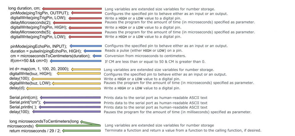
What does all this mean? I will first overview what the main parts of the code precisely mean and its functions. Starting off with the beginning code, const int(constant integer), this defines my TRIGGER and ECHO (from my ultrasonic sensor) pin #7 define my trigger & pin #10 as my echo. Also int(integer), defines my buzzer as pin #5. Algorithm (pinMode) configures the specified pin to act as a input or output. Therefore my TrigPin which sends a high frequency sound/signal, and triggers the timer. While the EchoPin receives the data. To calculate the distance from a ultrasonic sensor to an object you can easily use the equation, Distance = (Time x SpeedOfSound) / 2.
Algorithm Definition
Leading to my first milestone I ran into various problems. Those include not being able to properly connect my Arduino board to my computer. Since my Arduino pro micro was the most up to date board I had to download additional files so that it could properly connect to my computer. But because I didn’t know this, I spent 2-3 days reviewing how to connect my Photon board to my computer. Once I was able to connect my board to my computer I uploaded the provided code and started working on my circuit. But then again since my board was the most up to date model I had to change the code so that it could properly work with my specified code. For example I had to change the (constant integer) or (PIN) accordingly to my board. I then also wasn’t comfortable with the distance range therefore I changed it to 0-50 cm which means that the buzzer/LED or motor/LED dont constantly go off when an object is not relatively close to the user. Another problem that I faced was the actual configuration on the breadboard and how to properly wire my components so that I could efficiently run my circuit. I went over countless videos and went through various sites regarding how to properly use a breadboard and what each PIN in my Arduino board meant. I was finally able to work my circuit efficiently with both my LED and DC motor, but since I hadn’t received my switch yet i’m was not able to connect my buzzer following the schematic. Regardless, I was able to have a fully functional circuit that lit the LED when the distance between the ultrasonic sensors and another object came under or equal to 50cm. Moving forward I am planning on incorporating my switch, motor, and buzzer on my breadboard.
Starter Project

For my starter project I created the “useless” machine. Creating the useless machine was for the sole purpose of learning how to plan efficiently and how to solder. The “useless” machine consisted of; a motor, switch, PCB, motor, resistors, a battery pack, and a screw terminal. Each part has their specific function and without one of them this circuit wouldn’t work as efficiently. I began by coordinating how I was going to solder each component together. Then I began soldering each component together, I ran into a few problems when I was soldering, the components were constantly falling-out of place when I was trying to solder them. Therefore I used the helping hands and tried placing the components differently so that I could easily solder the pieces together.
Once I finished soldering my components I really tried integrating the new material I learned, I went through how each part works. I learned that the electrical motor I used is actually a ‘DC Motor’ and it is a machine that transforms electrical energy into mechanical energy in form of rotation. I also refreshed my memory on how circuits work specifically how switches and resistors affect the circuit, for example the switch breaks the circuit and interrupts the flow of electricity and in vice versa when you turn on the switch. As well as a resistor introduces a controlled amount of current. And as for the other components as the PCB, battery pack, and screw terminal were a huge factor to the actual effectiveness of the overall project, the battery pack powered the whole circuit, the PCB is used to mechanically support and electrically connect electronic components using conductive pathways, and finally the screw terminal was the electrical connector for both the motor and battery pack. Overall I with took various useful skills that will help me in the future when working on my main project, where I most definitely will use these skills to properly execute my project in the most efficient way.