
Hi, my name is Maeve. I am a rising senior at Urban. My starter project was the minty boost charger and my main project is a LED infinity mirror wall clock. I chose this project because I wanted to make something that would be useful and I could use every day. I became interested in engineering once I joined my schools XLabs class (engineering club) and took Advanced Physics.
Reflection:
My time at BlueStamp has been very beneficial and a great learning opportunity. Prior to this summer I had little experience with hands-on engineering and by the end of the program I became much more familiar and comfortable with coding and circuitry. Going into senior year with college on my mind, I have to figure out if I want to pursue engineering. BlueStamp has helped me learn more about engineering careers and majors from listening to speakers and talking to instructors. BlueStamp has made me interested in pursuing Environmental Engineering. If I were to come to BlueStamp again I would want to make something that has to do with Environmental Engineer or more focused on Mechanical Engineering.
Final Project:

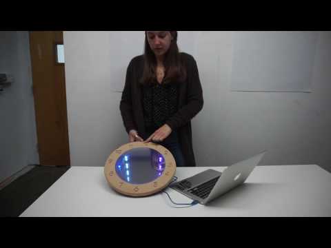
My final project was making an LED wall clock infinity mirror. My first step was connecting the LEDs to the Arduino with the code. I used a past Bluestamp students code (Ricardo) which uses the number of seconds since January 1, 1970 to show the current time. In order to make the infinity mirror, I placed a mirror behind the LEDs and the 2-way mirror film on a piece of acrylic so that you can see through the acrylic and mirror film and it reflects between the mirrors. For one of my modifications, I decided to mill numbers around the frame so that you can easily tell time. I used the Easel Inventible program to mill using the CNC mill. My second modification was changing the colors of the LED lights. Originally the code had red as hours, blue as minutes, and green as seconds. This made it a bit difficult to tell the difference between hours and minutes. I changed the colors so that the darker blue was the hour, the light purple was the minutes and the white was the seconds. Another modification I had in mind to do was connect and RTC to the Arduino that it could keep track of time on its own. Due to lack of time, I was unable to connect it successfully. One of my biggest challenges was constructing the clock. It was very hard to match up the top acrylic piece to be the same size as the inside of the frame in order for them to fit together.
Here are the materials I used to make this project:Bill of materials
Schematics for Arduino and LED lights:

Code for Clock:
#include <RTClib.h>
#include <FastLED.h>
#include <Time.h>
// How many LEDs in your strip?
#define NUM_LEDS 60
// For led chips like Neopixels, which have a data line, ground, and power, you just
// need to define DATA_PIN. For led chipsets that are SPI based (four wires – data, clock,
// ground, and power), like the LPD8806 define both DATA_PIN and CLOCK_PIN
#define DATA_PIN 3
#define CLOCK_PIN 13
#define TIME_MSG_LEN 11 // time sync to PC is HEADER followed by Unix time_t as ten ASCII digits
#define TIME_HEADER ‘T’ // Header tag for serial time sync message
#define TIME_REQUEST 7 // ASCII bell character requests a time sync message
// Define the array of leds
CRGB leds[NUM_LEDS];
void setup() {
Serial.begin(9600);
FastLED.addLeds<NEOPIXEL, DATA_PIN>(leds, NUM_LEDS);
}
void loop() {
if (Serial.available() ) //WAIT FOR TIME INPUT IN SECONDS FROM 1/1/1970
{
processSyncMessage();
}
if (timeStatus() == timeNotSet) {
Serial.println(“waiting for sync message”);
}//——————————————————--
else {
digitalClockDisplay();
// Updates the LED array so that each cell holds the color/time
leds[second()] = CRGB::White;//ACTUALLY GREEN
leds[minute()] = CRGB::Aqua;
leds[hour()*5-1] = CRGB::Blue;//ACTUALLY RED
// Displays the colors according to the time
FastLED.show();
delay(1000); // green:seconds blue:minute red:hours
// Clears the string so that the LED’s don’t stay lit
FastLED.clearData();
FastLED.show();
}
}
//————————————————————————
// FUNCTIONS
void digitalClockDisplay() {
// digital clock display of the time
Serial.print(hour());
printDigits(minute());
printDigits(second());
Serial.print(” “);
Serial.print(day());
Serial.print(” “);
Serial.print(month());
Serial.print(” “);
Serial.print(year());
Serial.println();
}
void printDigits(int digits) {
// utility function for digital clock display: prints preceding colon and leading 0
Serial.print(“:”);
if (digits < 10) Serial.print(‘0’); Serial.print(digits); } void processSyncMessage() { // if time sync available from serial port, update time and return true while (Serial.available() >= TIME_MSG_LEN ) { // time message consists of header & 10 ASCII digits
char c = Serial.read() ;
Serial.print(c);
if ( c == TIME_HEADER ) {
time_t pctime = 0;
for (int i = 0; i < TIME_MSG_LEN – 1; i++) { c = Serial.read(); if ( c >= ‘0’ && c <= ‘9’) {
pctime = (10 * pctime) + (c – ‘0’) ; // convert digits to a number
}
}
setTime(pctime); // Sync Arduino clock to the time received on the serial port
}
}
}
Milestone 3:
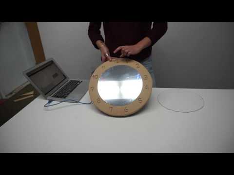
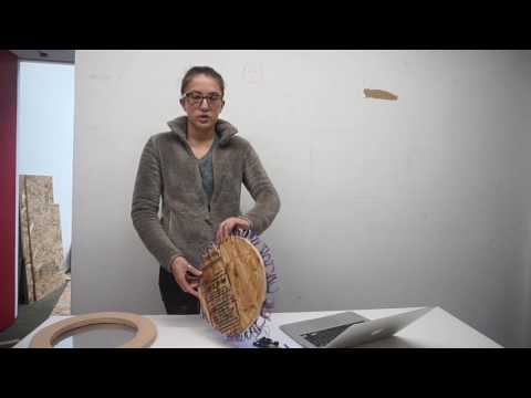
My final milestone was the structural and manual labor of assembling my clock. Since my last milestone, I recut my acrylic because it had several cracks and it affected the infinity mirror aspect of my project. I used a thicker acrylic and it didn’t crack as much as the first time. Since I wanted to have the acrylic fit perfectly inside the wooden frame, I filed the edges and the frame down to a 10-inch radius. I pasted the reflective film on the acrylic and hot glued it to the wooden frame. In order to read the clock I milled numbers using the program easel and placed each number in the designated place. To connect the clock to the frame I drilled 4 screws from the back so that you can’t see them on the front.
Milestone 2:
For my second milestone I created the physical structure of my clock. I milled the back of the clock out of wood to have a 12-inch diameter. I glued my 10-inch diameter mirror to the wood and superglued the LED lights around the mirror. I then milled my outer frame that will have the time displayed so that you will be able to tell the time. Since the LEDs and their wires were about 2 inches, I made the outer frame with an inner circle of 10-inch diameter and the outer diameter to be 14 inches. This way you can’t see the wires in the back. The final piece I constructed was the face of the clock. I cut the acrylic to have a 10-inch diameter so that is was able to fit snug inside the interior circumference of the frame. I covered the acrylic with one way reflective film so that you are able to see the LEDs but the lights are still able to reflect between the mirror on the back of the clock and the film.

Milestone 1:
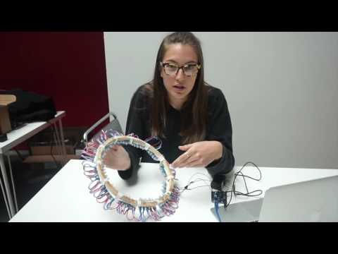
My first milestone was connecting my LED lights to the Arduino to have them function as a clock. I used the code from a past Bluestamp student (Ricardo) that programs the lights to blink and move as time passes. The code works by using the number of seconds since January 1, 1970 to show the current time.
Once you plug in the correct number of seconds, the multi-colored LEDs use green to show the seconds, blue to show the minutes and red to show hours. The clock can work without being connected to the computer as long as it stays connected to the 5V power source. Once it is unplugged from the 5V it turns off and the only way to turn it back on is to plug in back into the computer to download the code and input the updated number of seconds since January 1st, 1970.
Starter Project, Minty Boost Charger:
The minty boost charger works by converting the 3v coming from the 2 AA batteries to 5v in order to charge a phone. It uses the boost converter to step up the voltage by using the transistor to turn on and off the current. When the switch is closed, electrons flow through the inductor and create a magnetic field. When the switch is open the current will be reduced because of the resistance. The magnetic field created when the switch is closed is destroyed in order to maintain the current towards the load. In this scenario, the load is the USB outlet that will charge the phone. When the magnetic field is gone, the polarity will reverse and the voltage will increase. When the switch is cycled fast enough, the inductor will not discharge fully in between charging stages, and the load will always see a voltage greater than that of the input source alone when the switch is opened. I learned that you cannot solder while there are batteries in because it will overheat the batteries and they might break. Also, that there needs to be a specific voltage in order to charge a device so you cannot charge a phone with just batteries.
Great innovation!