DIY Robot Hand
My BlueStamp intensive project is a DIY robotic hand. The two portions of this project involve a glove lined with flex sensors and a 3D printed robotic hand. A user wears the glove, which controls the hand to mimic the motions made by the user.
Engineer
Kevin H.
Area of Interest
Computer Engineering, Mechanical Engineering, Physics
School
BASIS Independent Silicon Valley
Grade
Rising Senior
Reflection
When I first came to Blue Stamp in the beginning of June, I hoped to be able to apply my knowledge of math and science to create something tangible. However, I had absolutely no idea how difficult that task would be. I held the misconception that understanding a topic would make the its application easy. What I discovered was that that belief could not be further from the truth. In fact, engineering isn’t anything like what I learned in the classroom; while in the classroom I can expect round, nice answers and one logical solution to one problem, there are thousands of ways to solve a single task in engineering. Furthermore, I have to always be prepared for the worst. Things may fail in ways I could have never guessed, and it is up to me to figure out how to fix them. In summary, Blue Stamp showed me the persistence and creativity needed to become an engineer.
Final Milestone
My final project is a robotic hand controlled by a glove. In this project, one can control a robotic hand by bending his fingers. The hand will mimic the movements of the glove in real time. The original design that inspired this design can be found here.
For the third milestone, I connected the flex sensors onto the glove. These allow me to control the robotic hand by wearing the glove.

There were four changes made to the circuit. First, the voltage of the battery exceeded the functional range of the servos. Although this had worked in previous milestones, one of the servos finally bunt out and had to be replaced. As a result, I added a LM2596 buck switching regulator to decrease the voltage of the battery from 8V to 6V. Second, mistakes made when soldering the wires onto a blank PCB forced me to throw out the whole board and start over. Unfortunately, the four 33k ohm resistors were already attached, and desoldering them would be a time consuming task. I substituted the 33k ohm resistors with 57k ohm resistors for this milestone. A new circuit schematic is shown below. Third, the Arduino used to be powered by my laptop and a usb cable. This was replaced by another 5V battery pack. Finally, the addition of decoupling capacitors helped decrease voltage drops and noise, or fluctuations in the voltage. The electrolytic capacitors handled low frequency noise while ceramic capacitors handled high frequency noise.

The bill of materials for this project can be found here, excluding the 3d printed parts. Click here for the stl files to print the parts.
This milestone should have been relatively short, as I only had one objective: attach the flex sensors onto the fingers of the glove and use a blank printed circuit board (PCB) as a platform for the resistors and the analog inputs. However, I incurred many setbacks that caused a task should have taken a day to turn into a struggle that last over a week.
I began work by figuring out how to sew the flex sensors, PCB, and arduino onto the glove. I had to relocate the inputs of the circuit (entire right portion of the circuit schematic) onto the glove. I spent a lot of time trying to figure out how to best space them out before I deciding the arduino took up too much space, and it made the glove uncomfortable to wear. Therefore, I ended up only sewing the flex sensors and PCB. The flex sensors were sown onto the thumb, index, middle, and ring fingers of the glove. That allowed the glove to detect how much each finger was bent. The reason why there’s no flex sensor on the pinky finger is because the ring and pinky fingers move together on most people’s hands, and it corresponds with the pinky and ring fingers being tied to a single servo from the second milestone. The flex sensors are sown onto the hand with thread and made even more secure with glue. I used three types of adhesives trying to install the flex sensors: construction glue, super glue, and hot glue. To my surprise, the hot glue actually worked better than the super glue because the super glue stiffened the areas it contacted with while the hot glue remained sturdy yet flexible. The construction glue obviously failed because it was meant to be used on concrete or wood surfaces, but it was a good reminder to read the instructions more often. At the end of each flex sensor, the two leads were attached to wires and secured with heat shrink wrap.

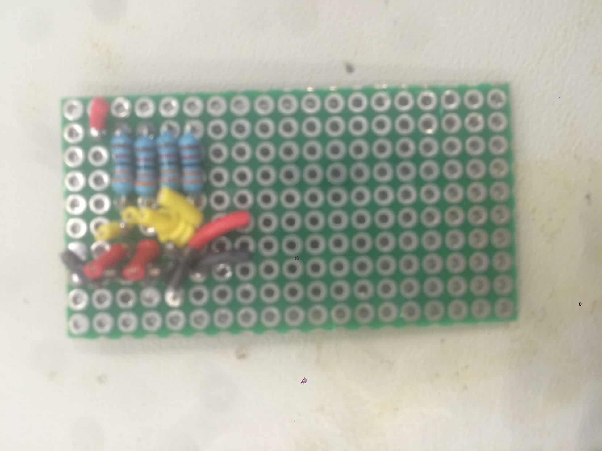
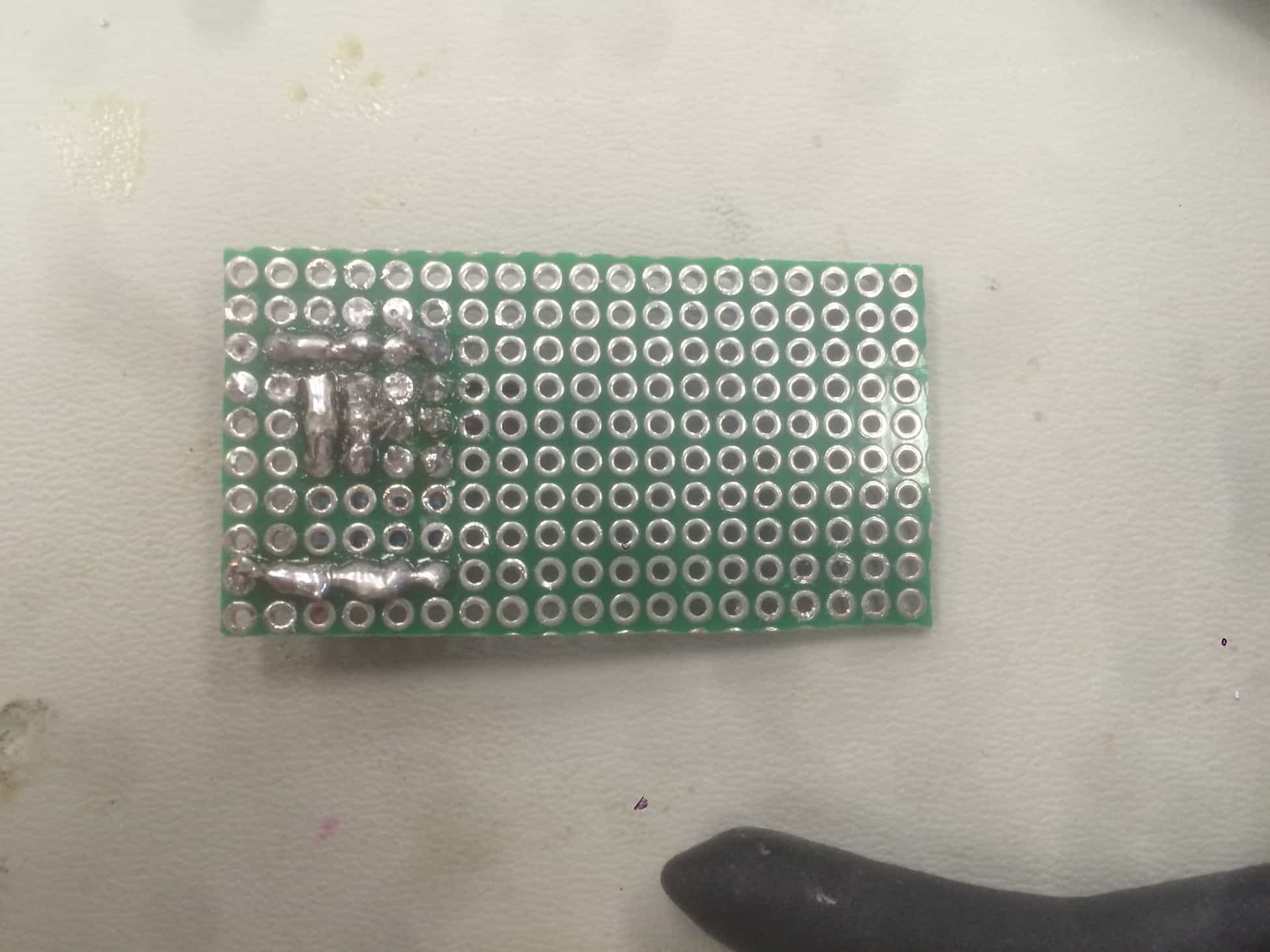
The other part attached to the glove was the PCB, which turned out to be one of my major setbacks. I found soldering the components onto the board very challenging because PCBs are insulated by a fibre-reinforced plastic (FRP) that is very good at repelling solder. This made making connections between the holes in the board very difficult, especially because I had to make numerous connections in a very small proximity and ensure there were no unintentional connections. I found that using the continuity setting on the multimeter was very useful for checking my connections. As I mentioned earlier, I actually had to repeat this process twice. During my first time, I had actually finished attaching all the components successfully; however, when I was attaching the PCB onto the glove, one of the wires came loose. Because everything was so close together, I had a tough time removing the remaining filaments left in the board and ended up melting the plastic of another wire in the process. Pictures of the old board are shown below.

That’s when I gave up and decided to start over on a new PCB. Fortunately, this time was faster because I found out I could strip a wire and lay it across multiple connections. This allowed me to solder connections to the wire without having to deal with the FRP coating on the PCB.
At this point, I should have been done with the final milestone. However, it wasn’t going to let me off that easily. As I was testing it, I managed to make it function for approximately one minute before I smelled something burning and saw smoke coming out of one of my servos. What I didn’t realize when this first happened was that the grounds of the servos and the flex sensors weren’t connected together, as their separation in the glove and hand made me completely overlook that. Instead, I assumed that the problem was with the battery. The functional range of the mg946r servos are only up to 7.2V. The battery, although listed at 7.2V, often delivers more than 8V. This has worked so far in the other milestones, but I thought the servos were just worn out at this point. A picture of the burnt servo is shown below.
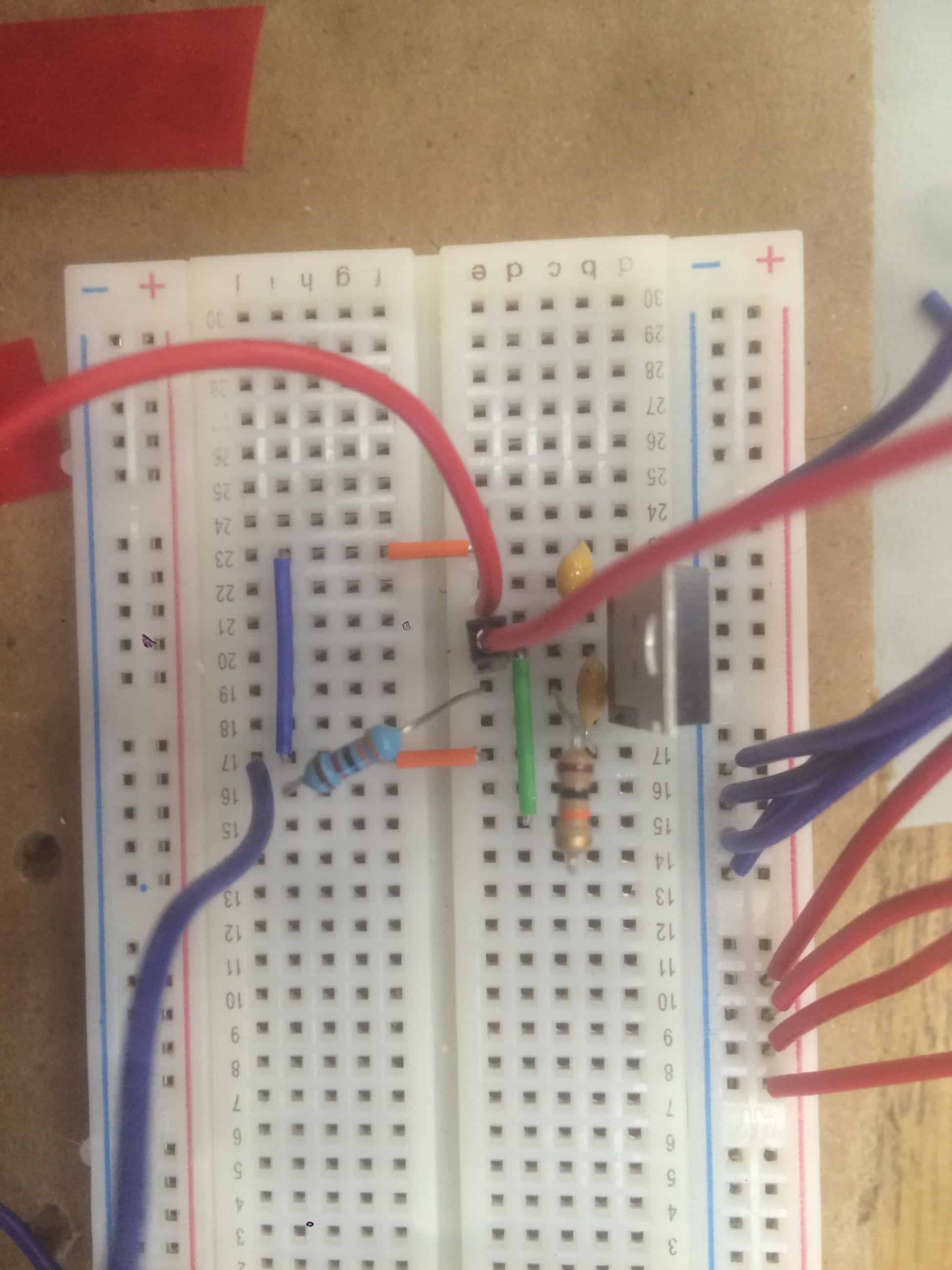
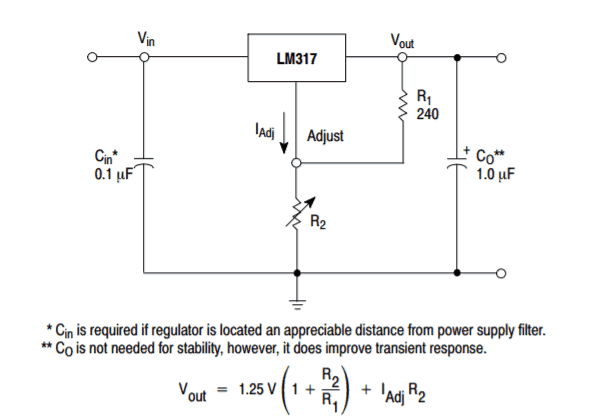
The first suggestion given to me was to use a LM317 linear voltage regulator to build a buck converter. A linear regulator takes an input voltage and creates an output voltage. In a buck converter, not only will the output voltage be more stable, but the output voltage can also be adjusted; the caveat of a linear regulator was that they couldn’t produce an output greater than the input voltage (otherwise known as boosting the voltage). The schematic shown below is how the buck converter should be built using the LM317 and the equation is how the resistor values can modify the output voltage.


According to the equation given, the ratio between R2 and R1 should be 3.8 to produce an output voltage of 6V. I used a 10k and 39k ohm resistor to create an expected output voltage of 6.125V. However, even after setting up the circuit and checking each connection again and again, I couldn’t produce the appropriate output voltage. Instead of producing a voltage around 6V, the output produced was 7.4-7.5V.
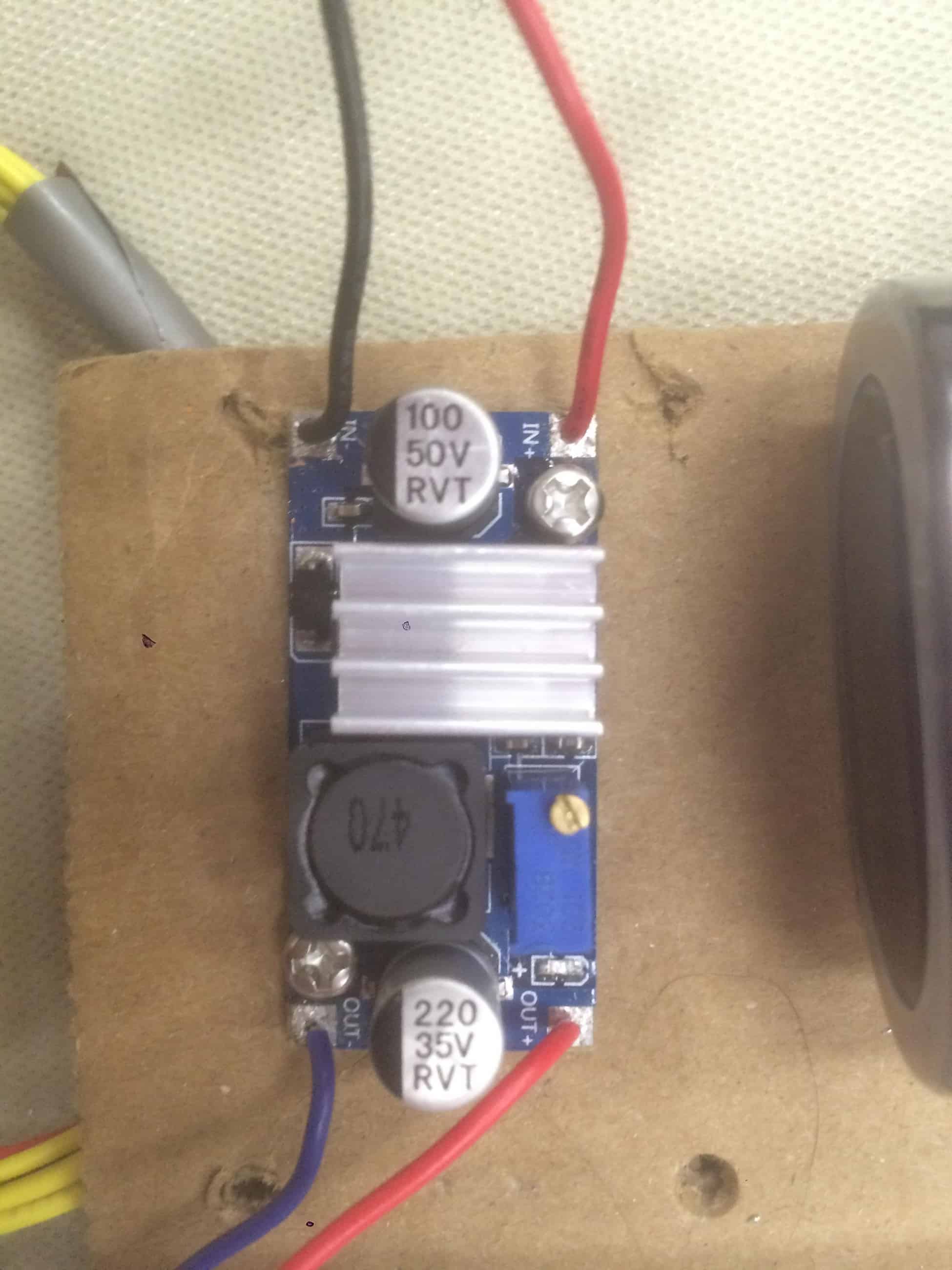
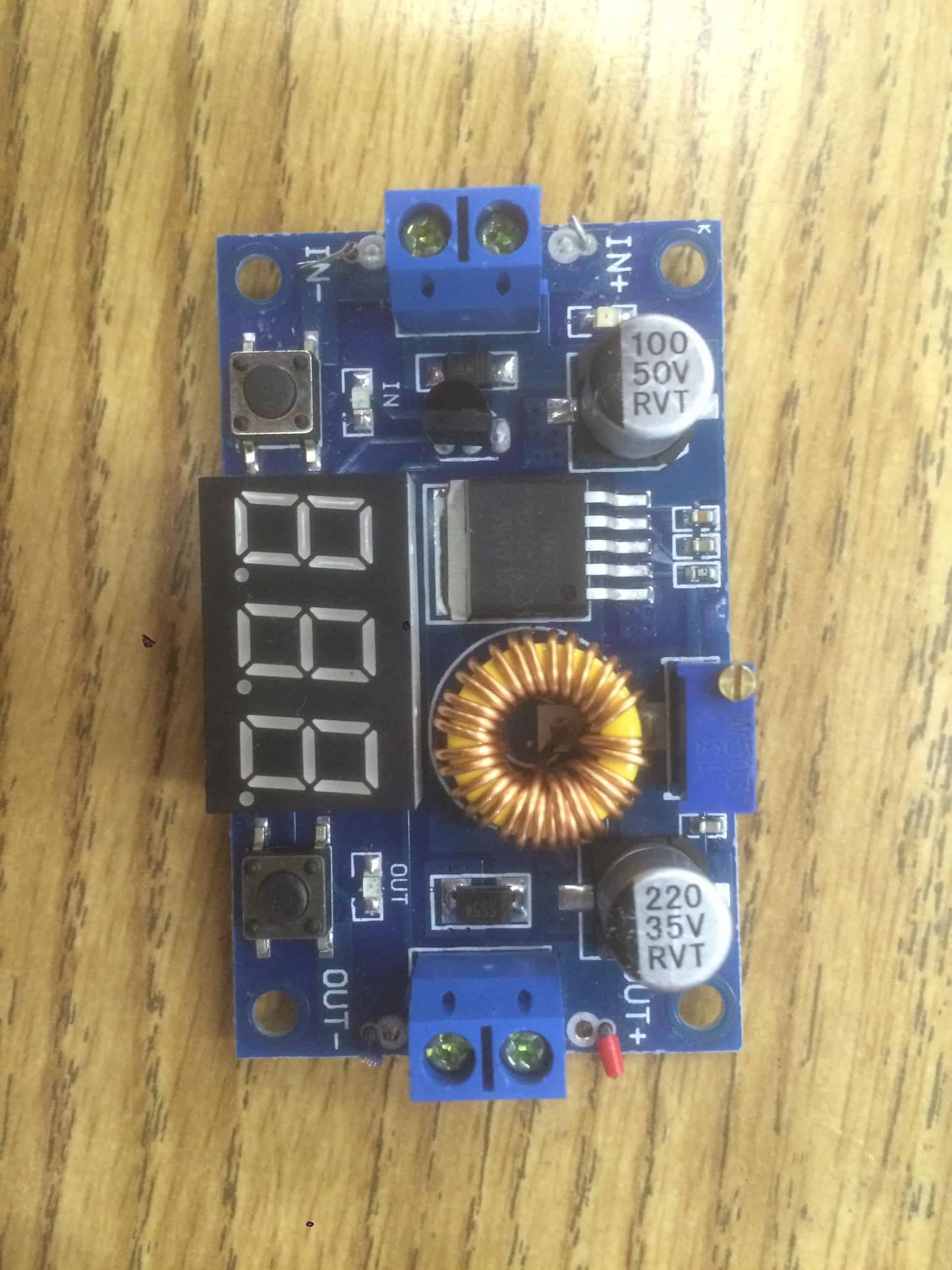
As the deadline approached, I used a prefabricated buck converter instead of the linear regulator. I tried two of them. The first one that I tied was the XL4015; it failed because changes in the power demand of the servo caused the voltage supplied by the converter to fluctuate significantly. The second converter that I used was the LM2596, which behaved much better compared to the first one. I scavenged a heat sink from the XL4015 for the LM2596 to improve its performance.
The code for this milestone is shown here. There were two primary changes made since the second milestone. First, I added several constants that correspond with the individual flex sensors. In the previous milestone, there was one constant for when the sensor was straight and another for when it was bent. These were replaced by custom constants because each flex sensor was bent more or less depending on which finger they were attached to on the glove. The calculatePosition() function was updated to include three constants when mapping the input of the flex sensors to the servos. The second change was changing reversing the input of the thumb servo (a0) on the range of 0 and 180 (eg. 10 would become 170, 70 would become 110, etc.). This is because I realized I attached the two lines backwards on the servo horn so that extending my finger on the glove would curl the thumb. Reversing the input in the code fixes this issue.
Second Milestone
My final project is a robotic hand controlled by a glove. In this project, one can control a robotic hand by wearing a glove. The hand will mimic the movements of the glove in real time. The original design this project is inspired by can be found here.
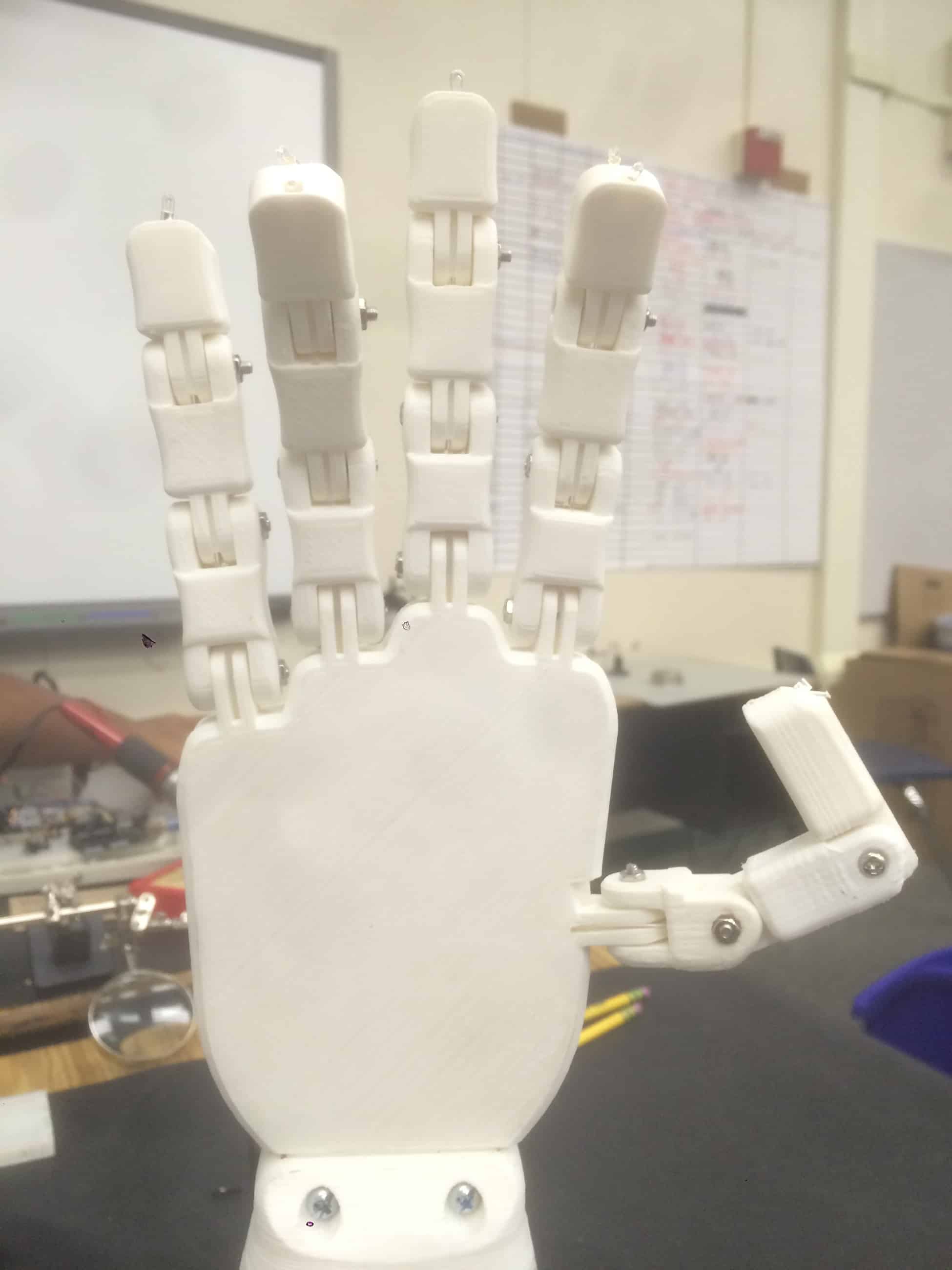
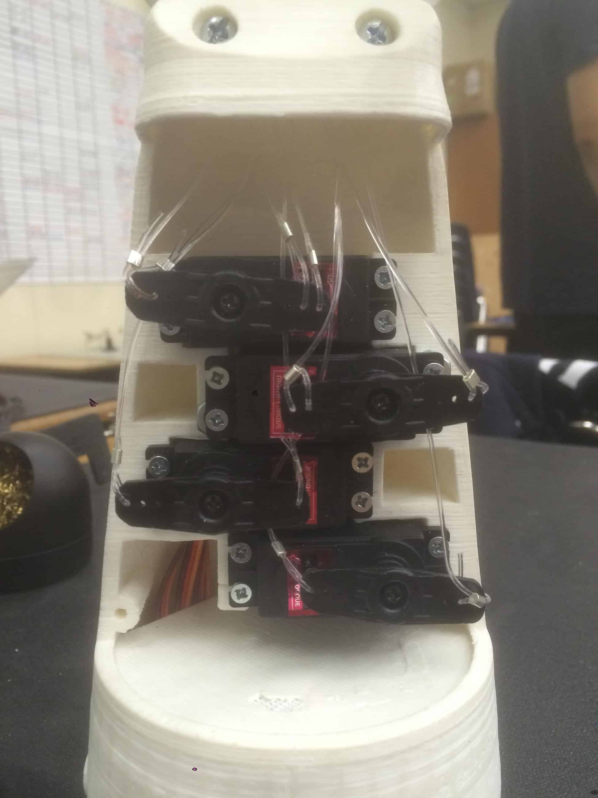
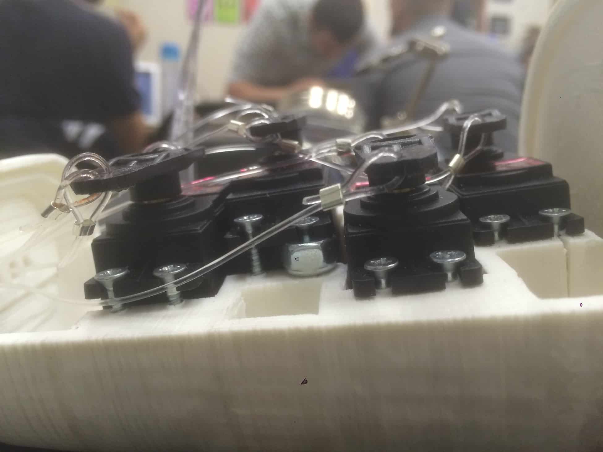
For my second milestone, I assembled the robotic arm itself. A picture of the assembled hardware can be seen below.

The electronics from the first milestone were mostly identical, with the exception of using four flex sensors and servos instead of five, and each pair of 10k ohm resistors connected in series were replaced with a single 33k ohm resistor. The servos were placed inside the forearm of the hand to control the fingers. The new circuit schematic is shown below.

The components used so far include an Arduino Uno board, four servo motors, four flex sensors, a 7.2 volt battery, a 1000μF capacitor, five 33k ohm resistors, fifteen M3x16 bolts, fifteen M3 nuts, fishing wire, twenty 2.5 mm diameter crimp tubes, sixteen 7/64-22 wood screws, two 5/16″ hex nuts, M4 x 1.0 x 32 bolts, and the 3D printed parts. Click here for the stl files to print the parts.
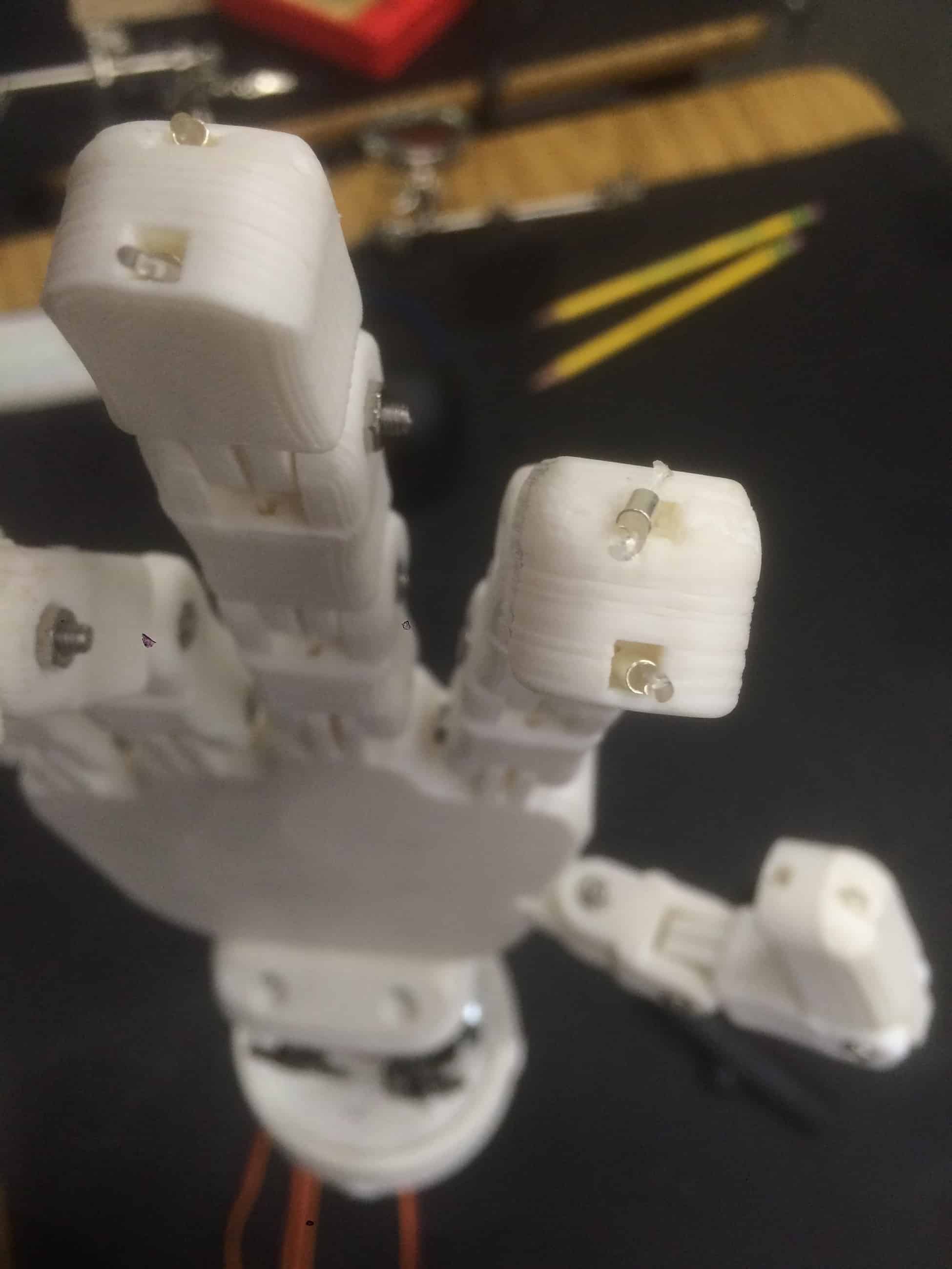
There are two portions to assembling the arm: the hand and the forearm. The hand is composed of 3D printed parts that are held together with the M3 bolts. One of the challenges that I faced was the quality of the printed parts. When I first assembled them, there was a lot of friction that made movement of the joints difficult. To fix the problem, I spent hours filing and sanding the parts so the fingers could bend easily. After all the digits were attached, two channels in the printed parts allowed fishing lines to be fed through them. The line on the front (palm side) side allows the finger to curl forwards while the line on the back side extends the finger. At the end of each line, crimp tubes serve as stoppers for the fishing line. The channels are too small to fit the crimp tubes through, so looping the fishing line through the tubes allow the line to stay in place when it is pulled. Pictures of the hand and the crimp tubes are shown below.
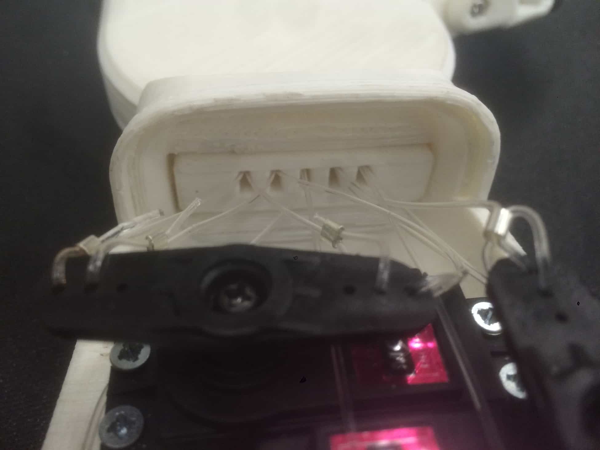
Each end of the servo horn is connected to the end of the fishing lines in each finger; one end is connected to the forward line while the other is connected to the backward line on one finger. Therefore, when the servos turn, they increase the tension of one line while providing slack to the other line. Because the servos are only capable of pulling, the lines act as tendons. The lines are looped through holes in the servo horns and held in place by crimp tubes. There are four important aspects to attaching the lines to the servo horns. First, the servos only rotate between 0° and 180°. To maximize the tension and slack applied by the servo, I removed the servo horns and wrote a reset program to set all the servo positions to 0°. Afterwards, I attached the servo horns so they were all vertical (perpendicular to the horn position shown in the picture above). This will maximize the displacement of each line. Second, although the servo horns won’t interfere in their current position, the lines may become tangled. I began wiring at the first servo (servo closest to the hand) to avoid this problem. Third, the first servo is responsible for both the ring and the pinky finger. Unfortunately, I found out that the servo is too weak to bend the knuckle joint of the pinky and ring fingers completely. To amend this in the future, I plan to attach a fifth servo so the fingers can bend independently with a greater range of motion. Finally, the lines are under much stress when the servo rotates, especially when the horn is near 0° and 180°. I crushed the crimp tubes with pliers to prevent the lines from slipping by increasing friction.
This milestone focused on hardware instead of software. However, a couple minor changes were made to the code. First, this milestone only utilized four servos instead of five, so there were only four analog inputs and PWM outputs used. Second, the values of the constants sensorStraight and sensorBent were decreased to accommodate the new 33k ohm resistors used. Other than these changes, the code is the identical to the one used for the first milestone.
First Milestone
My final project is a robotic hand controlled by a glove. In this project, one can control a robotic hand by wearing a glove. The hand will mimic the movements of the glove in real time. The original design this project is inspired by can be found here.
For my first milestone, I connected five flex sensors to five servo motors. Each flex sensor corresponds with a servo, and bending the flex sensor will turn the servo. The components used so far include an Arduino Uno board, five servo motors, five flex sensors, a 7.2 volt battery, a 1000μF capacitor, and ten 10K ohm resistors. The schematic for how this circuit was assembled is displayed below:
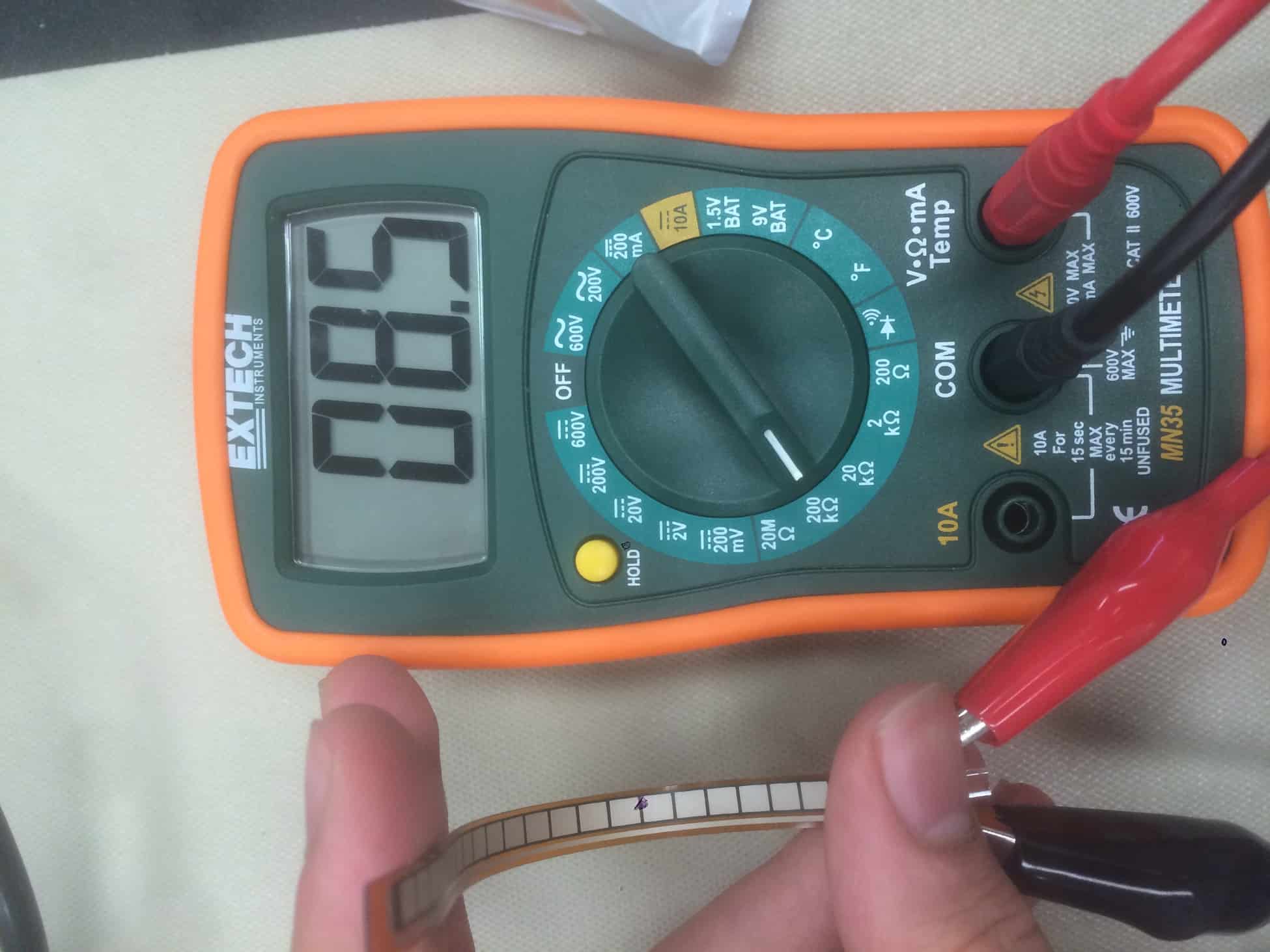
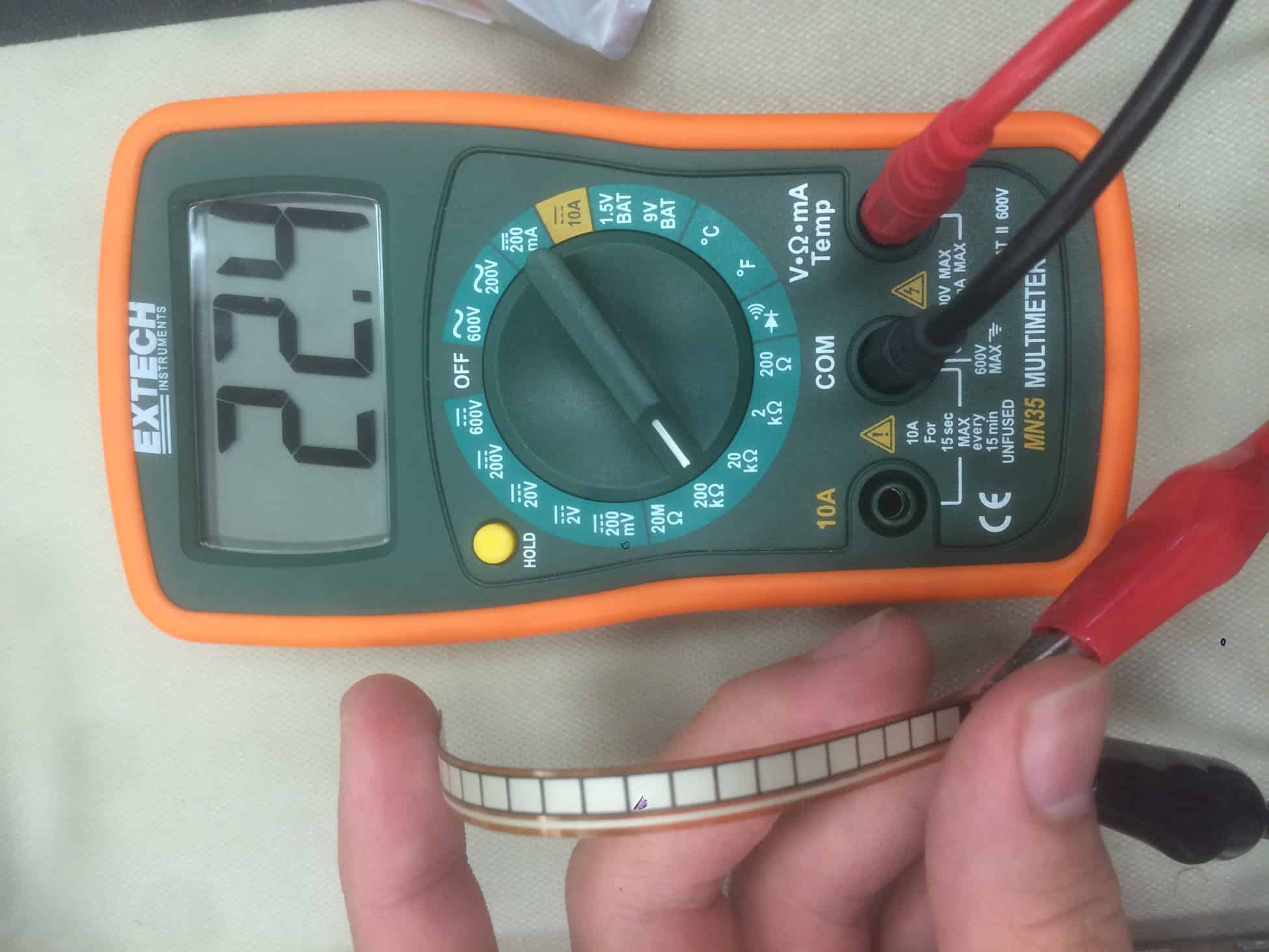
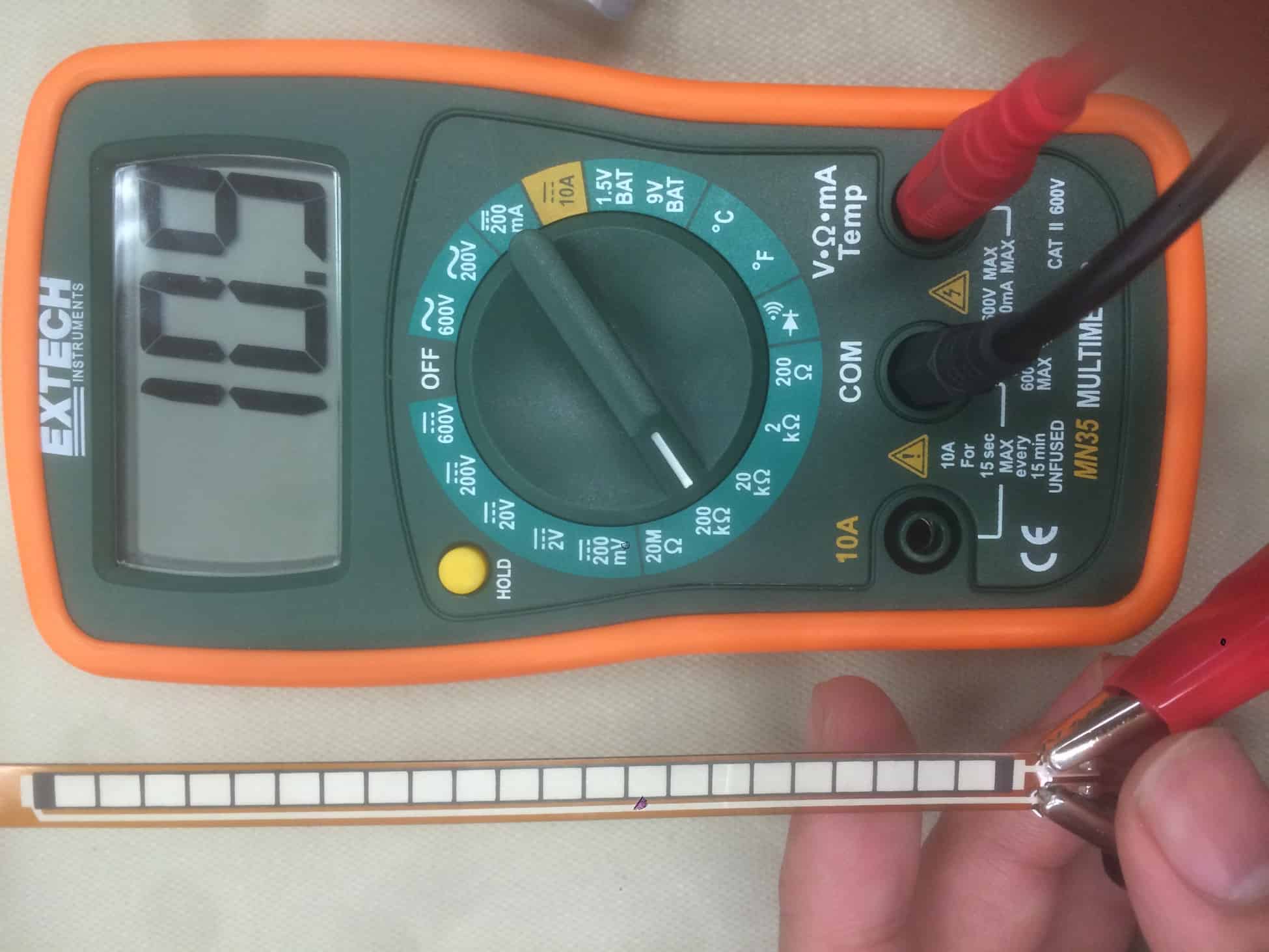
A signal is first produced when the flex sensors are bent. The flex sensors are connected in series with an equivalent of 20K ohm resistors (two 10K ohm resistors connected in series). A flex sensor is a variable resistor, which is able to change its resistance based on how far it is bent. The flex sensors used in this project are bipolar sensing and conductive-ink based. Conductive-ink based means that the flex sensor is filled with conductive particles such as carbon and silver, and bending it changes the proximity between these particles, which thus changes the resistance of the sensor; bipolar sensing means that they can detect which way the sensor is being bent (bending it towards the side with the striped pattern will decrease its resistance compared to its unbent state, and bending it away from the striped side will increase its resistance). The photos below show a flex sensor connected to a multimeter and how its resistance varies depending on how it’s bent. If you want to learn more about flex sensors, click here.

The analog signal is 680 when the flex sensor is unbent and 850 when the flex sensor is bent completely forward (for the purpose of this project, the flex sensor will not be bent backwards, so these are the two extreme states of the sensor). That analog value is then mapped to a digital PWM signal between 0 and 180, which corresponds to the angle and positioning of the servo arm. Servos differ from DC motors in that servo motors are more precise, and PWM input alters the speed of DC motors, while the signal determines the position in servo motors. For more information about the differences between these two motors, watch this video.
The servos themselves are connected to an external 7.2 V battery because the Arduino is unable to supply enough power to them. Besides just being connected to the battery, the servos are connected in parallel with a capacitor, which stabilizes the power supplied to the circuit. The 1000μF capacitor serves as a bypass capacitor, which is a component that handles fluctuations in the power source. They by accumulating and releasing energy during dips or spikes from the power supply. To learn more about the how capacitors smooth out voltage ripples in the circuit, click here.
Besides just the hardware portion, software is required to make the Arduino function. Click here to view the entire source code. As a brief explanation, the creation of the constants, inclusion of the Servo.h library, and the declaration of the servos happen before the setup. In the setup portion, the servos are initialized; servo.attach() lets the Arduino know which servo is connected to which output pin. In the Arduino loop, servo.write() outputs a value between 0 and 180 to determine the position of the servo. On the other hand, the Arduino board takes input with analogRead(), which is what reads the voltage at the point between the resistors and flex sensor. The function that I wrote myself, calculatePosition(), maps the input from analogRead() to generate the output between 0 and 180.
Ah…the good old 555 IC. This looks pretty cool, Kevin. Make sure you have the schematic down–I’m going to want you to explain it to me! Looking forward to what you continue to do with the summer.
-Mr. Hrin
I never got to use anything as cool as flex sensors when I took my circuits classes. I do have a question–the writing on the Arduino board schematic is a bit hard to read, but I was curious as to where/if you have the high voltage going into the board? Doesn’t it need an input DC voltage so it can generate the 5 V that’s being applied to the flex sensors? Great Work!
-Mr. Hrin
Hi Mr. Hrin!
Thanks for asking! I responded via email to the first comment, but I’ll leave both responses as comments in case school faculty email are deactivated over summer. As for the first comment, I held onto the circuit schematic for the exploding star organ, and I’m definitely expecting to be grilled on how the components work together. For the second comment, flex sensors are pretty fun to work with! Additionally, my laptop is connected to the Arduino with a USB cable to provide power. Let me know if you have any more questions!
Best,
Kevin
This is really neat, Kevin! You’ve even got your own version of the carpal tunnel. I’m glad that I’ve been able to get updates periodically throughout the summer (this is a subtle suggestion that you should tell the rest of your physics crew that they should send me an update too ;)). I do have to take issue with one thing you have in your description–I believe that the lines are acting as tendons, not ligaments. In anatomy, tendons attach muscle to bone, and thus they are responsible for the motion of limbs/digits, while ligament are responsible for connecting bone to bone so that different bones don’t go sliding off in weird directions. In the hand, the ligaments would be responsible for keeping the finger bones aligned so that they curl properly when they get pulled on. In your hand, the ligaments would be the pins/rivets that the finger pieces pivot on. Sorry if it’s nit-picky, but that’s what you get when you have your science teacher review your project. I really liked the way that you fit the servos into the forearm area–I’m sure that it took some doing. Looking forward to your next update!
-Mr. Hrin
Hi Mr. Hrin!
It has about the same range of motion as William Cao’s hands. I’ll be sure to fix that on that website; all I can really say is that’s why I’m taking post-AP physics instead of bio! Putting the servos into the forearm was definitely a challenging task (you can see that I actually cracked the plastic in the Servo 2 Padding image), but attaching the lines onto the servo horns was much more difficult in my opinion. I’ll tell the others to say hi!
-Kevin