
Hello, welcome! My name is Karlota A and I am a rising sophomore at DSST: GVR High School. I have been in love with math and science since a young age and by coming to Blue Stamp I gained exposure in a STEM field that will hopefully set me up for success in the future. During my time in Blue Stamp, I created an LED mood-light that would go through a series of different colors and respond accordingly with certain colors when it experienced a change in volume or a detected a different sound.
Checkout my school’s website at http://www.dsstpublicschools.org
——————————————————————————-
Bill of Materials:
To create the LED mood-light cube you would require certain tools and materials. The tools you use are up to user preference but the essential materials to put it together like I did are the following:
One of the most important materials that is needed is an Arduino Uno that would normally cost between ten to twenty dollars on sparkfun, adafruit, and even Amazon.
Another material that you would need is a picobuck LED driver that can be purchased online athttps://www.sparkfun.com/products/11850 for $15.
The heart of this project, the high power LED, can be purchased also from Sparkfun for $15. https://www.sparkfun.com/products/8718
Next to power your Arduino you would need an Ac/dc power supply that can be bought from amazon for $8.
From Amazon I ordered eight 12×12 sheets of plexiglass (in inches) for the price of $30 total. But I later found out that if you want them to be a certain size you could stop by a place such as Home Depot and by it in that size or have it cut to your specifications.
I also used glitter spray paint that can be obtained from any arts and crafts store for about $8 at the least. I also used glitter to touch up but it is not a necessity but rather it is more of a preference.
Code information
Cross-Fade:
For the first round of coding I did something called Cross-Fade to fade my colors smoothly through its sequence. Cross-Fade is when I would dim one color in the RGB LED and make the other two brighter to make a different color. An RGB LED is an LED that contains the colors blue, red, and green and the frequency of those colors can be raised to 255 at the highest and 0 at the lowest. For example, if I were to keep the red and the blue at 255 and dim the green to a 0 I would end up with the color purple. But then to get colors like teal, orange, and pink I had to play around with the code since nothing on the internet seemed to work for my project. Shown below is the Cross-Fade code that I used to fade all my colors smoothly without random colors interfering.
https://gist.github.com/jamesotron/766994 Strobe Effect:
Another type of coding that I did was the strobe effect. The strobe effect is a light effect that would quickly turn the LEDboff and then turn it back on really fast but it would turn it back on to the next color in the sequence. This code was easier to do but at the beginning the only colors that I had were blue, red, green, and yellow. In order to incorporate more colors I had to do some research on how to mix the colors to produce other colors that would blink just as fast. Once I became familiar enough with how the code works I decided to incorporate Cross-Fade into my strobe code and managed to speed it up in order to get a strobe-like effect.
Steps to build project:
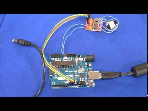
First you would have to do some coding and upload that code onto the Arduino. I used the code that I provided above and uploaded it to my arduino. You would then have to solder the wires onto the LED to the positive side of and then solder those wires onto the LED driver. Red goes to in1 blue to in2 and green to in3. Then solder wires into vin+ and vin. Vin+ goes to Vin and Vin goes to gnd(ground). You would then solder three wires onto the negative side of the LED and connect those to pins. I chose to have green go to pin 9, red to pin 10, and blue to pin 11. Afterwards I tested my LED by connecting the Arduino to the adapter and plugging it into the wall. Afterwards I proceeded to make a 6 by 6 base and divide it in half to be 3 by 3 and printed it to fit my cube once it was done. While I waited for it to print I went ahead and cut the acrylic to 5 1/2 by 5 1/2 and spray paint those with the diamond paint to diffuse the light and touched it up with the spare glitter. Then I mounted my acrylic pieces once dry and put them on the base. I then drilled a hole to one side of the cube to fit the adapter cable through. I then sealed everything with an epoxy and finished it off with some more glitter!
http://m.instructables.com/id/Led-Candles-Moodlight/
Schematic and pictures:


Reflection on Challenges:
Throughout my time in Blue Stamp engineering I faced many obstacles while putting my main project together. My main project was an Arduino LED mood-light candle that would go through a sequence of colors fading smoothly through every color. At the beginning of this program I knew nothing about coding and as I slowly built up on the basics of it I was able to incorporate more colors into the sequence yet I was unable to have a fading effect. I would have my lamp fade from orange to green to pink or only have certain colors flash once and then others appear multiple times. I wanted a smooth transition and in order to have that I had to write my own code all from scratch and look up my how to do color blending and how to mix red green and blue to get colors such as orange or teal.
——————————————————————————-
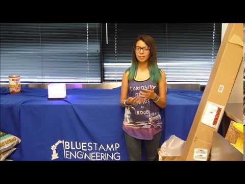
Milestone 3:
This is my last milestone, where I was finally able to complete and demonstrate my project. In the end of it all I built my base and the case for the LED and Arduino but was unable to get the capacitive touch sensors or the microphone to work due to the thickness of the plexiglass. I was able to get the lamp to smoothly fade through every color once and start all over without turning off or turning to the color white before starting the sequence once more. Blue Stamp Engineering taught me a lot of important lessons and helped me develop as an upcoming engineer. This program helped me meet people that are a lot like myself and opened up doors to the fields of engineering that I hope to someday work in even if I was unsure of myself at the beginning of the program due to programming skills that I lacked but developed in my six weeks here.
——————————————————————————-
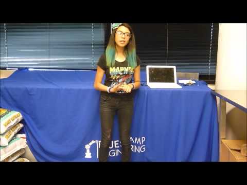
Milestone 2:
For my second milestone I incorporated a microphone into my mood-light candle so that it would pick up on sound and change between red and blue colors depending on the sound it hears. I struggled with the code and had many obstacles such as the code not working right or only having two colors yet I was able to get two of the basic colors which got me to a point where I was able to make it react to sound. I was also able to begin working on my base for my cube and a box for my Arduino to work as a form of protection. Another thing that took me a lot of coding and research but paid off in the end was that I was able to get the color orange and pink in my sequence of colors
——————————————————————————-
Milestone 1:
For my first milestone I had programmed my arduino to the point where I had it do a strobe effect since I was still new to coding and I managed to make a makeshift light diffuser out of paper towels. I programmed it to have only few colors and only orange appear once. I was able to get the LED to flash quickly rather than to fade it slowly and smoothly.
——————————————————————————-
For my 2015 Blue Stamp project I built Sparkfun’s gram piano. The gram piano is controlled by capacitive sensors that when they come in contact with your finger the electrons flow through your finger into the board and push the insulated plates together to transport a small amount of current from you to the board through conduction to make the board able to produce the sound of one full piano octave at varying pitches. This was a fairly easy project yet many obstacles occurred when it was time to actually turn on the keyboard and try to play it. The problems I faced were fairly easy to fix with some revisions on the soldering and current that the circuit contained. Here is the link to the website: https://learn.sparkfun.com/tutorials/gram-piano-assembly-guideh
I’m very proud of you and im sure that this program will help you develop your potential