Hi! My name is Kaley, and I am a rising senior at Cathedral High School ( http://www.cathedralhs.org). I had heard of BlueStamp through the new engineering director at my school. Even though I had little knowledge of engineering and no experience in robotics, I felt that it would be a great opportunity to take. My starter project is the Sparkfun Gram Piano, a mini keyboard piano with capacitive touch sensors. For my main project, I am building a vertical hydroponic farm, a method of growing plants using mineral nutrient solutions in water.
Main Project: Vertical Hydroponic Farm
Reflection
Spending my summer in BlueStamp has paved my path towards engineering. I started the program with no experience, and for the first few weeks, I was extremely confused, especially when I tried explaining how my each of my projects worked. Yet, through time and help from the instructors, everything became more understandable. Nevertheless, I was still confused at some points because my entire intensive project was a challenge. But once I solved each challenge (with time), I became more confident in my project and in myself (sometimes). This experience has taught me that saying “please” will encourage it to work. Also, even though some days were extremely frustrating, it felt AWESOME once everything started working properly. Environmental engineering might have not been my first choice in the beginning, but an artificially grown plant can change the world!
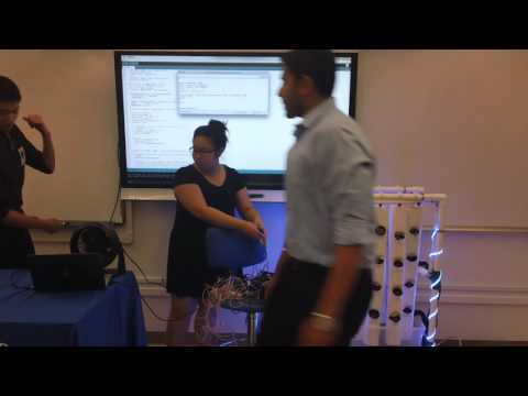
Parent’s Night Presentation
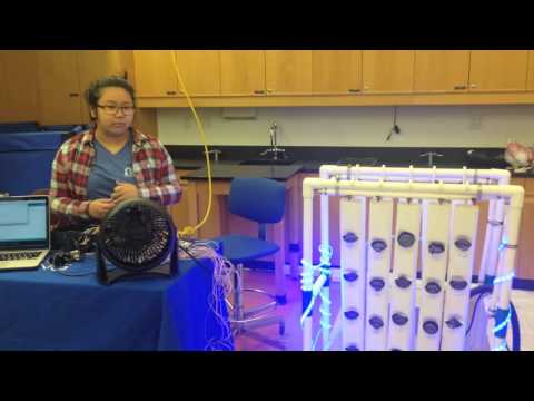
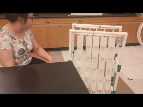
Final Milestone: IT’S ALIVE!!!
 After six weeks, Squirtle finally works! The pipes are no longer leaking in the wrong places. The water circulation flows as planned: from the tub to the PEX pipes to the drip emitters and downspouts and back to the tub. Also, the electronic components almost all worked as planned. The fan and the temperature sensor works well with the relay and the Arduino; however, because there were loose connections with the pH doser and the relay, sometimes the peristaltic pump glitches. However, they all worked awesomely for the showcase. I was a proud mother.
I did not have time to code the lights, so I connected them to a 12v battery, so they remain permanently on, and stuck them onto the farm. It was beautiful.
Challenges:
I faced a lot of challenges in this project. Coding was definitely not my strong suit, but with the help of the instructors I was able to figure out much, and I feel confident that if anything goes wrong with the farm, I would be able to fix it. Also, using power tools for the first time for an entire day will result in sore arms, well at least for me. But it was fun playing – I mean using – the tools. No humans were hurt during the production of this project.
Third Milestone: Nervous System (Electronics)
In order to control the climate indoors, I included a thermostatically controlled circulation fan that works along a temperature probe. This system works due to a channel relay. A relay is an electromagnetic switch operated by a relatively small electric current that can turn on or off a larger electric current. The fan is connected to the relay, which is connected to an Arduino, a microcontroller board. So, I coded the temperature sensor to measure the temperature in the area, and if it is over 78°, then the fan will automatically turn on. Like the fan, the pH doser and the solenoid valve is also similarly connected to the relay and to the Arduino. The doser is a peristaltic pump. It pumps fluid through the tubing by a rotor that pinches the tube to force the liquid to move to the other end of the pump. The pH sensor measures the pH of the water solution, and if its readings are more than or less than a certain pH, the Arduino sends a signal turns on the relay, which turns on the pH doser. The solenoid valve, an electromechanically operated valve controlled by an electric current to act like a switch, controls water entry into the PEX tubes. If the water meter measures the flow to be more than 2 liters per minute, then the solenoid is programed to stop the flow of water. Also, in order to increase the efficiency of the farm, I included blue grow lights opposed to green lights since plants absorb blue and reflect green. Therefore, this specific wavelength will be best for photosynthesis.
 Also, in order to protect the electronics from the water, I put the relays and the Arduino into a box. I drilled a hole in order to stretch the flow switches, the pH sensor, the temperature sensor, and the pH doser to the tub of water.
 Challenges
A challenge I faced while completing this milestone was coding since I had no prior (good) experience. The original designer of the project had provided his code on his webpage; however, it was extremely complicated for me to understand, and I was not able to download the library used. Therefore, I had to slowly figure out what each part does before I rewrote the code and combined them into one. Also, I had a lot of loose connections because I didn’t solder correctly. So, I had to re-solder them and secure them using electrical tape and heat shrink.
Even though this part of the project was extremely frustrating, after I had figured out each part, and got everything working correctly, it was very rewarding.
You can download my code here!
These are my schematics:
Hand drawn….please don’t judge 🙂

Second Milestone: Circulatory System (water circulation)
 Since I built the support structure in the first milestone and cut all of the water supply lines using PEX pipes, for my second milestone, I added netting pots to the pockets of the downspouts and connected all the pipes and secured them using a crimping tool (which was extremely hard to control). Since all the water lines were connected, I finally tried testing the submersible pump. As the water was circulating, I noticed that there was leaking around the drip emitters and in the connection of the water tubes with the PEX pipes. So, I applied a lot of silicon sealant around the leaking areas. Even though that somewhat ruined the clean look of the pipes, there was eventually no leaks!!! I also cut a tube (that looks like a large straw) that will serve as the water return system. It will be placed on an angle so that the water will flow, like a slide, directly to the tub of water.
Moreover, I started working on the ClimateBot, which will control some of the environmental components of the farm, including the lighting cycles and the circulation fan. The fan will be thermostatically controlled; if the temperature sensor detects that the weather is above 78°, it automatically turns on the fan.
Challenges:
There were several challenges I faced. When I was adding the netting pots, I noticed that the size of the openings were either too large or small in size. Because I opened the pockets without specific dimensions, most of the nets did not fit, so I had to use a heat gun in order to shrink or expand the openings
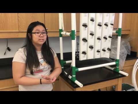
First Milestone: Skeletal System (Support Structure and Grow Towers)
 For my main project, I am building a vertical hydroponic farm, which is a method of growing plants using mineral nutrient solutions in water without soil. The pH levels, nutrient levels, lighting cycles, and ventilation fans will eventually be maintained by the Arduino. My first milestone was building the support frame and the grow towers using PVC pipes, PEX tubes, and downspouts, which were all cut using the hacksaw. The PEX pipes are the main water supply lines. So water will travel from the tub with the pump to the PEX tubes, and flow down from the drip emitters to the downspouts and gutter. The water will ultimately return to the tub. Afterwards, I cut the pockets using a dremel, which is a power cutting tool, and I opened them using a heat gun and a self constructed wood template tool and a table leg. After including the netting pots, these pockets will be the home to my plants.
 My project is based on a Hydroponic Farm designed by Paul Langdon; however, because the size of his project was not suitable in my current “environment,” I resized it by half.
Challenges:
I faced several problems when building this structure, such as actually using the tools. I gradually became accustomed to them, but I have battle scars to prove that they are difficult to tame. For instance, while using the hacksaw, I had trouble keeping it straight and parallel to the table in order to cut precisely. Also, keeping the downspouts clamped securely to the table was hard due to the fact that they are hallow within.
Also, the initial assembly was not perfect. The pipes were connected askew, so I had to trim them. The pockets were hard to open because we did not have the necessary tools. We first used a hammer, but it did not work well. Eventually I made a wooden tool and used a table leg in order to open the pockets to a perfect diameter.
Moreover, I tested the submersible pump with the PEX pipes for the water supply. Because the tubing and the PEX pipes were not fastened tight enough, there was a lot of leaking, which I have to resolve.
CAD Drawings
Hydroponic – Assembly 1 Drawing 1 (1)


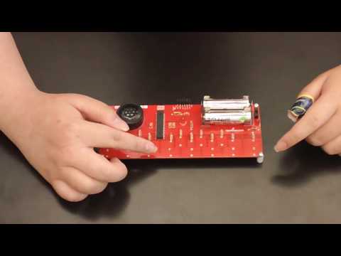
Starter Project: The Gram Piano
How it Works:
The piano is powered by two double AA batteries on the printed circuit board. Once the power switch is turned on, the right LED will light up to confirm that it is on. Afterwards, the center LED will blink in order to indicate that it is ready for use. Each LED is connected to a resistor in order to limit the current produced by the LED to prevent from shorting. There are also capacitors present to store energy and to smooth out the voltage before the microcontroller. The microcontroller holds the memory of the circuit and is preprogramed to play a melody when the button is pressed. Through the potentiometer, a variable resister, the octaves of the keys can be changed. The piano is played using the capacitive touch keys. Through an interference of electric fields of the keys and our fingers, the microcontroller will detect the change in voltage and signal the playing of the correct notes.
Challenges:
This was my first time learning how to solder correctly, so the beginning might have included some difficulties, but afterwards, everything was good (enough)!
The speaker of the circuit was not soldered correctly, so some of the notes were playing. Through some help, I had to desolder and re-solder the speaker, and eventually the sound was fine.
Also, I didn’t quite understand how the mini keyboard worked at first. I was especially how the capacitive touch sensors worked. However, with the help of researching on Google and the instructors, I was able to fully understand and explain in my own words how the entire circuitry works.