Solar Panel Sun Tracker- Phone Charger
My main project is the Solar Panel Sun Tracker. It has a bonus of being a phone charger as it uses free clean energy. The project follows the Sun’s movement across the sky. To track the sun, it uses a servo system controlled by an arduino for panel positioning.
Engineer
Kaasha M.
Area of Interest
Chemical Engineering
School
Saratoga High School
Grade
Incoming Sophomore
Demo Night
Demo Night
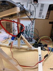
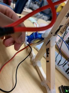
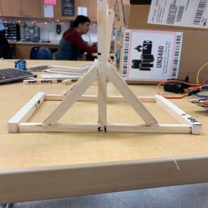
My main project is the solar panel sun tracker as well as being a phone charger. My 2nd milestone was to build the support structure for the panel to sit on and mount the servo onto the structure. A few days back, I was working extremely hard with the handsaw to cut thick pieces of wood for my structure. Before cutting, I had to take measurements to make sure that the panel could sit on the structure with appropriate widths. But the next day, thankfully, I built the whole structure with a packet of precut pieces called dowels that had a variety of different thickness. I chose the pieces that would support my structure best and cut lengths with a handsaw. It went much faster and it was much less time consuming. After cutting the appropriate pieces, I glued it with hot glue. I also drilled two holes into the support beam for the rod to go through. The panel sits on a steel rod and the servo has been mounted on with hot glue as well. Additionally, the panel has 2 wood support beams on the back of it with drilled holes for the rod to go through. I also soldered 2 photo resistors to jumper wires and hot glued those to my solar panel which will be used to track the sun. Throughout this process of finishing my 2nd milestone, I learned how to use a drill and handsaw. I also learned how to solder components to wires. I also struggled with this process because when I was gluing the components for my support structure, I did not put enough hot glue so the structure was wobbly. I had to glue 2 or 3 times before it being pretty sturdy. My next milestone will be connecting everything together which includes calibrating my servo to make it sun tracking, and doing the charger portion of my project.
Third Milestone
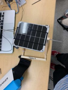
My main project is the solar panel sun tracker as well as a phone charger. My 3rd milestone was calibrating my servo and coding my Arduino to be sun tracking and to finish the charger portion of my project. So basically, if I shine light on the photoresistor, it will rotate the panel in the direction of the light movement. Also, if I plug in my phone into the charging port, it will charge. Basically, how it works is that my photoresistors which are light dependent resistors sense the light and tell the microcontroller in the Arduino which tells the servo motor to rotate the panel in the direction of the light. The servo motor will rotate the panel in the direction of where the photoresistor’s resistance is low which means the light will always be falling on it. The charger uses a boost converter which steps up voltage, a DC Jack Adapter Cable that connects from PC board to the solar panel and a lithium battery. Throughout this process of finishing my 3rd milestone, I learned to code an Arduino better and troubleshoot. I struggled with this milestone a lot as my servo fried so I had to replace it and my code wasn’t working. After writing new code, it worked. My next milestone which will be modifications will be to add a RGB LED to display the amount of battery left in my phone and to paint my support structure.
Second Milestone
First Milestone
Circuit Diagram
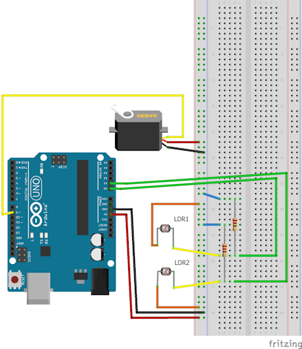
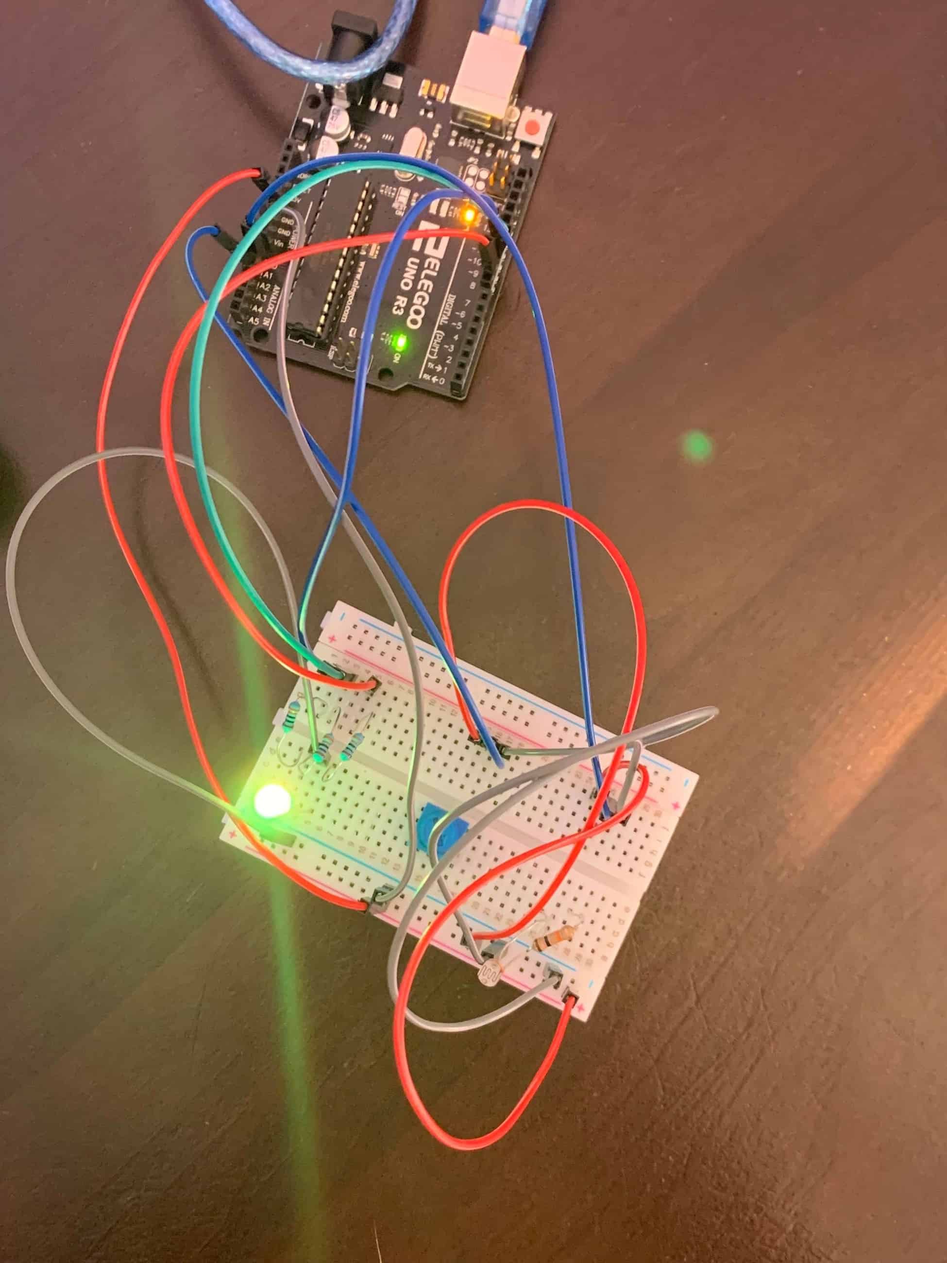
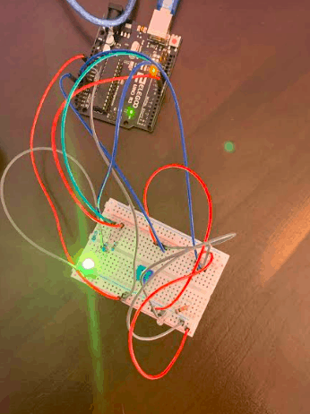
My first milestone was to figure out how to use the photo resistor which is a light controlled variable resistor to turn the servo and trigger the LED. Basically, after I upload my code to the Arduino, the servo will turn and the LED will light up. The servo rotates by the amount of light given to the photo resistor. Before coding the Arduino, I actually had to hook up all these components to a breadboard. It took me a while to figure out how to code the Arduino use the photo resistor to turn the servo as well as triggering the LED. But, after some time it worked! Unfortunately after some time of working, the Arduino was facing some issues uploading and it couldn’t find the right port to connect to which is Arduino Uno. After doing some research and watching some videos, I figured out how to solve the issue. I learned throughout this process was how to solve issues if the Arduino couldn’t upload the code. My next milestone will be to build the support structure for the solar panel to sit on and to mount the servo onto the structure.
Starter Project: RGB LED Night Light
RGB LED Night Light
HOW IT WORKS
Circuit Diagram
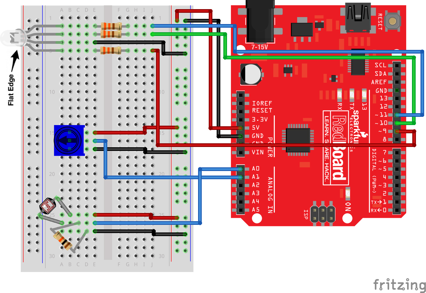
Code for RGB LED Night Light
https://github.com/kaasha1/RGB-LED-Night-Light-