Portable Centrifuge System
This Portable Centrifuge System serves the purpose of separating cells in a fluid suspension. The Centrifuge can be made with easily accessible materials but has a very significant function, especially in the field of Biotechnology. Through the use of this portable centrifuge, very cellular level information can be discovered.
Engineer
Juhi M
Area of Interest
Biomedical Engineering
School
Cupertino High School
Grade
Incoming Senior
BlueStamp Engineering
BlueStamp Engineering exposed students to Mechanical and Electrical Engineering and was an experience which pushed us to find solutions for unexpected as well as expected issues.
Challenges I faced included precision while using a Hand Dremel, proper placement of the electrical wiring and secure positioning among the various materials used. However, these challenges allowed me to seek innovative solutions.
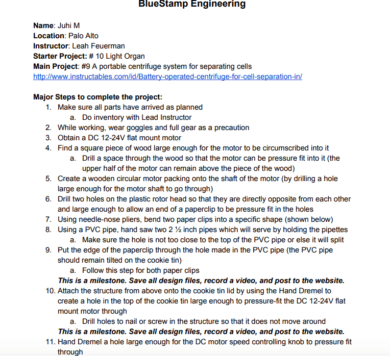
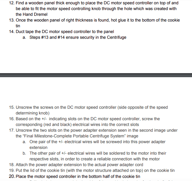
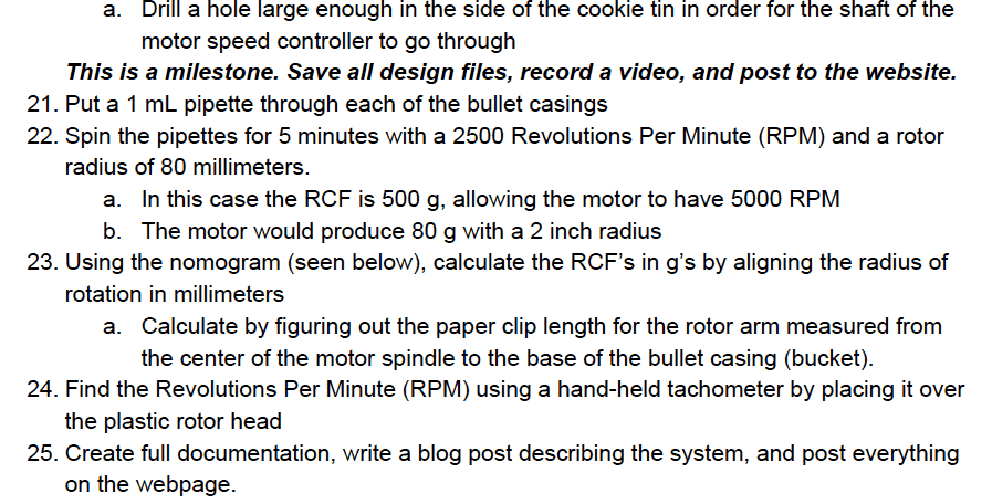
Build Plan- Portable Centrifuge System

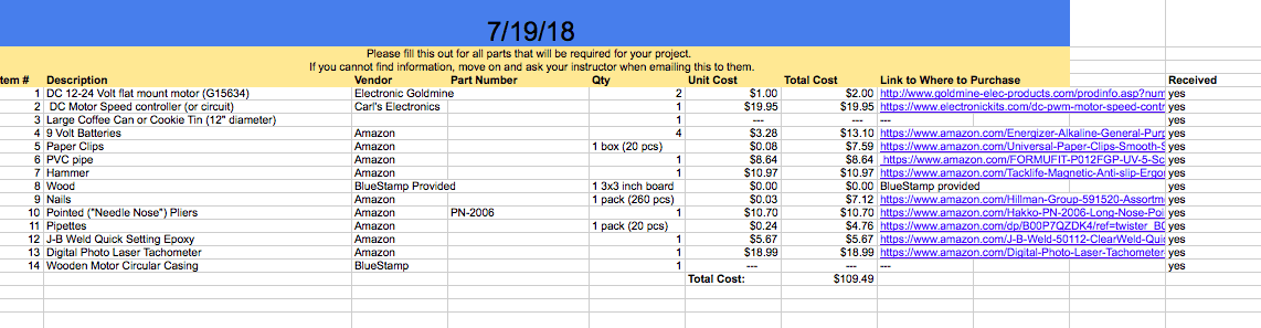
Bill of Materials- Portable Centrifuge System
Final Milestone
Final Milestone- Complete Portable Centrifuge System
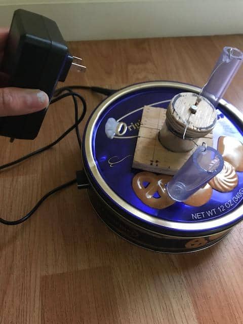
My Final Milestone is the fully functioning Portable Centrifuge System.
Materials Used In This Milestone:
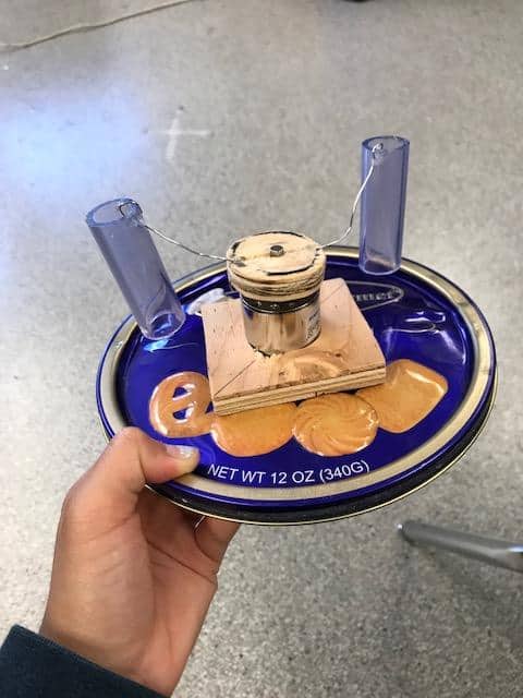
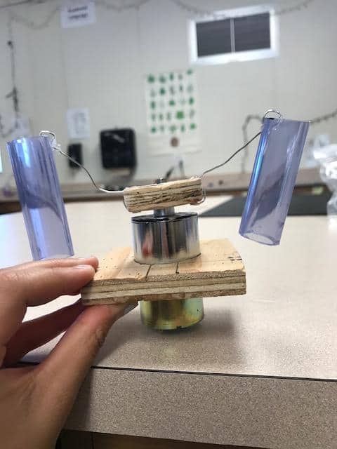
- Motor Structure attached to the upper half of the cookie tin
- DC motor speed controller attached to the bottom half of the cookie tin (main box)
- Soldering Iron
- 2 Positive and 2 Negative Electrical Wires
- Power Adapter
Set-up:
- Unscrew the screws on the DC motor speed controller (side opposite of the speed determining knob)
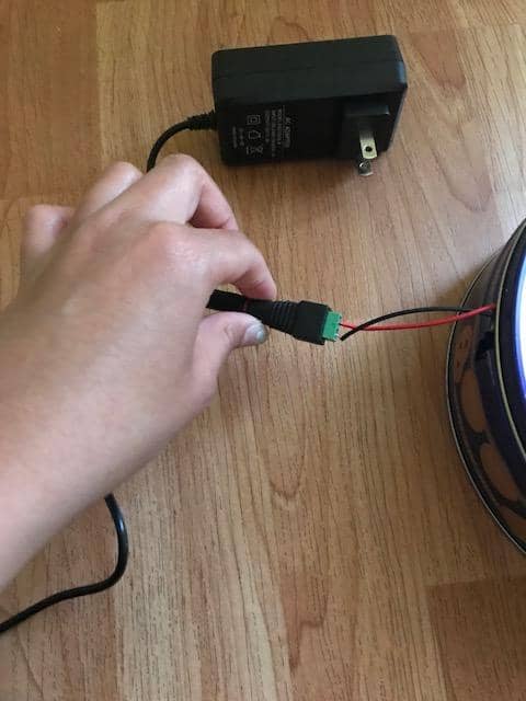
- Based on the +/- indicating slots on the DC motor speed controller, screw the corresponding (red and black) electrical wires into the correct slots
- Unscrew the two slots on the power adapter extension seen in the second image under the “Final Milestone-Complete Portable Centrifuge System” image
- One pair of the +/- electrical wires will be screwed into this power adapter extension
- The other pair of +/- electrical wires will be soldered to the motor into their respective slots, in order to create a reliable connection with the motor
- Attach the power adapter extension to the actual power adapter cord
- Put the lid of the cookie tin (with the motor structure attached on top) on the cookie tin
- Plug the power adapter into an outlet
- Turning the knob of the DC motor speed controller, watch the PVC pipes spin due to the motor
Purpose of Final Milestone
The Portable Centrifuge System serves the purpose of separating fluids based on density. This separation is achieved by spinning a pipette-holder at a high speed. In this case, the motor provides the high-speed rotations. The centrifugal force is known to push heavier material to the bottom of the pipette. The Portable Centrifuge System is especially beneficial in the field of Biotechnology. The most fascinating aspect of this creation is that it was made with simple materials. However, the set-up was difficult as it included maneuvering around various challenges, such as placement of wires and using the Hand Dremel.
- One pair of the +/- electrical wires will be screwed into this power adapter extension
- The other pair of +/- electrical wires will be soldered to the motor into their respective slots, in order to create a reliable connection with the motor
Third Milestone
Third Milestone- Bottom half of Portable Centrifuge
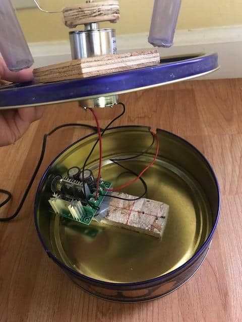
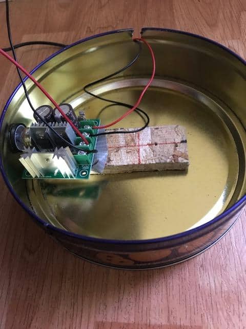
My Third Milestone includes attaching the DC motor speed controller to the bottom half (the main box) of the cookie tin.
Materials Used In This Milestone:
- The bottom half (main box) of a cookie tin
- DC motor speed controller
- Wooden Panel
- Duct Tape
- Hand Dremel
Set-up:
- Drill a hole in the side of the bottom half of the cookie tin
- Make sure the hole is large enough for the knob on the side of the DC motor speed controller to pressure fit through it
- If the hole is not large enough, use a Hand Dremel to make it larger
- Place a thick wooden panel on the bottom of the cookie tin, right below/next to the hole which was created by the Hand Dremel, allowing the speed controlling knob of the DC motor speed controller to appear through the cookie tin
- The purpose of creating this hole is so that the speed of the Portable Centrifuge can be controlled from the outside
- The panel should be thick enough for the motor speed controller to be placed on top and the knob of the controller should be able to go through the hole that was previously created using the Hand Dremel.
- To make sure the panel does not move, it can be hot glued down
- This structure can be seen in the third image under “Final Milestone- Complete Portable Centrifuge System”
- Place the DC motor speed controller on the wooden panel and make sure the knob can securely fit through the hole in the side of the cookie tin
- Once the placement of the speed controller has been finalized, duct tape the DC motor speed controller to the wooden panel to ensure that the controller will not move around.
- Using the Hand Dremel, create a “U” shape in the top/side of the cookie tin, out of which the wires screwed to the extension of the power adapter, can rest in while the lid of the cookie tin is attached.
Purpose of Third Milestone
The Third Milestone serves the purpose of nearly completing the building of the Portable Centrifuge system. This Milestone demonstrates the completion of the placement of all required materials as well the required use of the Hand Dremel. The last aspect of the project is attaching the electrical wiring as well as using the power adapter to power the centrifuge.
- If the hole is not large enough, use a Hand Dremel to make it larger
- The purpose of creating this hole is so that the speed of the Portable Centrifuge can be controlled from the outside
- The panel should be thick enough for the motor speed controller to be placed on top and the knob of the controller should be able to go through the hole that was previously created using the Hand Dremel.
- To make sure the panel does not move, it can be hot glued down
- This structure can be seen in the third image under “Final Milestone- Complete Portable Centrifuge System”