Hi! My name is Josh and I am a rising sophomore at the Hebrew Academy of Nassau County. I chose to attend Blue Stamp Engineering because I wanted to immerse myself in an environment where I was able to enhance and learn new engineering skills. My starter project was the Minty Boost Portable Charger and my main project was a screw-propelled vehicle.
Reflection
I find it amazing how 6 weeks can change your perspective towards engineering. I came into Blue Stamp with barely any experience in coding or mechanical engineering. Additionally, I boldly decided to create my own student-defined project with the risk of not finishing it by the end of the program, so I was especially nervous with what to expect from this experience. Throughout the program, I faced a multiple complications, but managed to overcome them and display a fully functioning project at the end.
The instructors had a perfect balance between helping you with your problems and distancing themselves from you so you could troubleshoot them yourself. They would never directly help you unless you haven’t already failed. This may seem a bit harsh, but I thank them for teaching me valuable life lessons. Not only has Blue Stamp taught me about motors, micro-controllers, and soldering, but it has also taught me different ways to think around problems and persevere through obstacles. Because of Blue Stamp, I have developed a strong passion for engineering and have decided I want to pursue a career in engineering in the future.
Resources
Please contact me at [email protected] if you have any questions.
Onshape 3D models: https://www.onshape.com/
* Onshape is a 3D CAD system that allows everyone to design their own models for free online. In order to access my 3D models, you must create a free account on Onshape.com. From there, you will be able to search my public models using the keyword: Vilkas.
Bill of Materials:
https://docs.google.com/spreadsheets/d/1qAlDhums0R3K3BPd4I7hBiqQ03paq7AGEdiSTvJCc6E/edit?usp=sharing
Final Milestone
For my final milestone, I connected the Arduino and Motor Shield to a Wii remote.
Before explaining how I connected the Arduino and Motor Shield to a Wii remote, I must explain a change in the way the screw-propelled vehicle moves. Previously, I thought that if one screw were to rotate clockwise and the other, counter-clockwise, the vehicle would move forwards. When trying that same pattern of movements while controlling the vehicle with the Wii remote on concrete, I noticed that instead of moving forwards, it pivot turned, sort of like a tank. I can’t conclude that this is how the screw-propelled vehicle behaves in other terrains, like mud. Therefore, I hope to test my screw-propelled vehicle in the future, in a variety of other terrains in order to truly understand and exhibit its capabilities.
![]() Originally, I planned on controlling my screw-propelled vehicle with a Play Station 2 controller. After multiple days of unreliable connection and wiring difficulties, I decided I needed to take a different approach. I came across using a Wii remote as another option for controlling the vehicle via Bluetooth. The Wii controller came with a USB host shield and Bluetooth dongle, which I stacked on my Arduino and Motor Shield. I was able to sync the Wii remote to the USB host with the Wii library. By combining the Wii’s library code with the code I previously used for my Motor Shield, I was able to control the movements of the screw-propelled vehicle. I used different buttons on the D-pad of the Wii remote to control the vehicle in different directions.
Originally, I planned on controlling my screw-propelled vehicle with a Play Station 2 controller. After multiple days of unreliable connection and wiring difficulties, I decided I needed to take a different approach. I came across using a Wii remote as another option for controlling the vehicle via Bluetooth. The Wii controller came with a USB host shield and Bluetooth dongle, which I stacked on my Arduino and Motor Shield. I was able to sync the Wii remote to the USB host with the Wii library. By combining the Wii’s library code with the code I previously used for my Motor Shield, I was able to control the movements of the screw-propelled vehicle. I used different buttons on the D-pad of the Wii remote to control the vehicle in different directions.
In an excerpt of my code, you can see the different ways my motors rotated in response to the press of the left button:
if (Wii.getButtonPress(LEFT)) {
myOtherMotor->setSpeed(200);
myMotor->setSpeed(200);
Wii.setLedOff();
Wii.setLedOn(LED1);
myOtherMotor->run(BACKWARD);
myMotor->run(FORWARD);
Serial.println(“Backwards”);
delay(15);
}
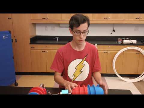
Milestone #3
In my third milestone, I programmed the Arduino and Motor Shield to move my motors.
The Motor Shield allows you to drive DC motors, controlling both their speed and direction. I downloaded the Motor Shield library and modified the code to match what I wanted my screw-propelled vehicle to do.
In order for the screw-propelled vehicle to move, the motors need to be programmed so that they spin either clockwise or counter-clockwise. In order to move forwards, one screw spins clockwise and the other, counter-clockwise. The opposite happens when it moves backwards. When one screw spins and the other remains still, the vehicle pivot turns left or right. But, what makes this vehicle unique is what happens when both screws spin in the same direction. When both screws spin either clockwise or counter-clockwise, the vehicle moves left and right, sort of like how a crab walks. For now, all this code does s tell the screw-propelled vehicle to move left or right. In the future, I will program it to move forwards, backwards, and pivot turn left and right.
This code will serve as a test to make sure my motors run properly. The code tells the motors to spin forwards, but the Arduino doesn’t know which way the motors have been placed. Therefore it just tells the motors to spin one way or the other:
Serial.println(“Left”);
myOtherMotor->run(FORWARD);
myMotor->run(FORWARD);
for (i=0; i<255; i++) {
myOtherMotor->setSpeed(i);
myMotor->setSpeed(i);
delay(5);
}
for (i=255; i!=0; i--) {
myOtherMotor->setSpeed(i);
myMotor->setSpeed(i);
delay(2);
}
Milestone #2
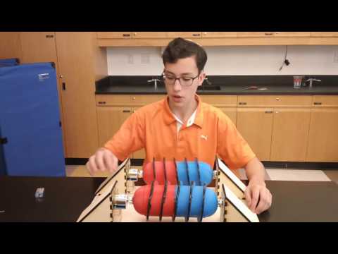
In my second milestone, I connected the screws to my finished chassis.
 After my first milestone, I went back to Onshape, a 3D modeling software, and created wedges. This is where the screws and the motors would be securely attached. I created all five faces of the wedge to be laser cut. Each face of the wedge utilized a finger joint design which when connected, allowed the wedge as a whole to withstand much more force. I also attached a hub on each screw in order to hold a metal rod. This rod went through a rolling bearing in the wedge and added support and fluidity to the screw when it spun. In order to attach the motor to the base of the chassis, I crafted wooden blocks and screwed them into the base of the chassis. The chassis was completed when I screwed the wedges onto the base and bored holes in the base and into the wedges for the wire to attach to the Arduino.
In addition, I painted on liquid rubber to the edges of the screw in the hopes that it will give the screws more traction on harder surfaces.
Milestone #1
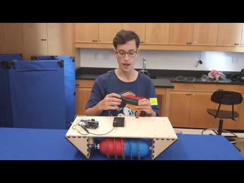
In my first milestone, I designed the four half screws, assembled them, and secured the motors onto the full screws.
Almost all my parts so far have been custom designed by me, and then either 3D printed, laser cut, or cut using a power tool. In order to create these custom parts, I needed to find a 3D modeling software that was easy to learn and use, but also produced great results. So I spent the first and second weeks completely immersed in 3D modeling software trying out multiple programs such as SketchUp, FreeCAD, and Onshape. I found Onshape to be the easiest to use. In Onshape I produced my screw pontoons. I decided to build the screws in halves since the 3D printer had its limitations as to how big it could print. When connected the screws are 10 inches long. There was a peg and a hole on one side of each screw so that the connection between the two halves would be much stronger. I didn’t realize that when an object is 3D printed, the plastic expands a little bit. Therefore when I tried fitting the peg in the hole, it just wouldn’t fit. I learnt how to use a Drummel and spent the entire day decreasing the size of those pegs until they fit. I used industrial glue on the pegs and flat face of the two halves when fitting them together and used a hot glue gun around the edges where the two halves met. Another problem I encountered with the screws was that the holes where the motor shaft would be inserted were too small. Therefore, I learnt how to use a power drill and drilled out the holes for the motor shaft to enlarge them.
At first I had ordered two 6V right-angle motors to be attached to my screws. By the time I had 3D printed the screws and had seen how big the were, as well as taken an estimate as to how big the chassis would be, I decided I needed bigger motors. So I switched to two 12V motors which I attached to my screw pontoons with a clamp hub.
Starter Project
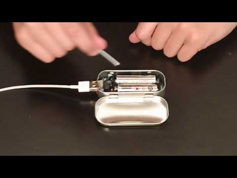
For my starter project I built the Minty Boost portable charger. I chose this for my starter project because it has a very practical use in my daily life.

The Minty Boost portable charger converts 3v inputted by two AA batteries into 5V. The IC chip is purposefully programed to switch the bridge on and off in a consistent pattern creating a change in electrical current in the inductor. The inductor will then oppose this change by transferring its stored magnetic energy into electrical current. The diode prevents the 5V from decreasing back to 3V. This process will occur repeatedly before the current is boosted to 5V. the IC chip will monitor the outputted voltage so that it stays at a constant 5V. Additional parts of the circuit include capacitors, which store excess energy and allow the circuit to flow smoother, as well as resistors that dissipate excess energy so that the correct amount of needed energy is outputted to the phone.