
Smart Garden
The Smart Garden monitors temperature and moisture in order to notify you when plants should be watered. The plants can then be monitored remotely. The Smart Garden uses Arduino.
Engineer
Jonathan S
Area of Interest
Mechanical Engineering/Electrical Engineering
School
Ramaz Upper School
Grade
Incoming Sophomore
- An Arduino Uno or Elegoo Uno
- A soil moisture sensor product number YL-69
- Water level Sensor
- A relay (make sure that it will switch with 5 volts)
- Water pump motor
- Breadboard
- 4 pin I2C LCD
- thin, flexible, plastic tube
- A lot of wires. Also, a wire stripper, soldering wire, and a soldering iron.
Reflection
When I began BlueStamp, I knew next to nothing about engineering or Arduino. However, I learned a lot over the course of this summer. A lot of this is due to the independence that Bluestamp provides. When a problem arose, I tried to solve it myself. For me, independence is crucial to learning for two reasons. First, I have a very difficult time learning anything when I am being told exactly what to do. My new- found self-reliance will allow me to create my own ideas.When I leave BlueStamp, I will create more projects using Arduino and maybe learn Raspberry Pi. In the later future, I would likely become an engineer but I do not know which type.
Final Milestone
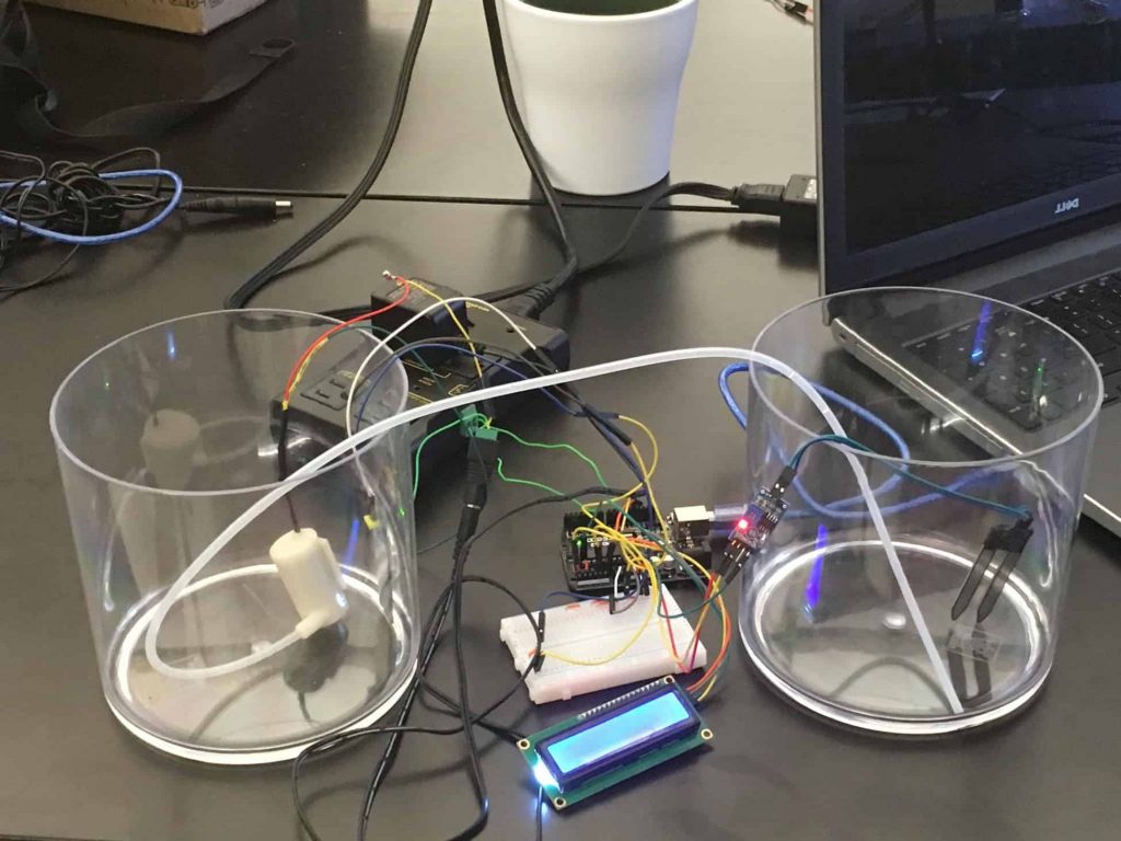
For Milestone #3, I got my water pump to work. I also edited the code so it asks for the value the soil moisture sensor should read before the soil is considered dry and the water pump is turned on.
My water pump requires 6 volts of electricity to operate. This means I can not control it directly with an Arduino because an Arduino can only supply 5 volts. For this reason, I had to use a relay. A relay is a switch that opens and closes the circuit if a relatively small amount of electricity is supplied to it. My code will start supplying electricity to the pin connected to the relay when the plant should be watered. When the plant is sufficiently watered, said pin is turned off. Here is a sample of the code.
void watering(){
if(soilCheck>=preWat){
while(soilCheck>=postWat){
digitalWrite(10,HIGH); //10 is the pin connected to the relay, writing high supplies 5 volts. (skipping code related to LCD)
}}digitalWrite(10,LOW);
I have two ideas for modifications. The first idea would allow the user to say how often they want their plant watered rather than only being able to give a potential value for the soil moisture sensor. The second idea is to add a sun lamp that would turn on and off based on the time of day.
if(soilCheck>=preWat){
while(soilCheck>=postWat){
digitalWrite(10,HIGH); //10 is the pin connected to the relay, writing high supplies 5 volts. (skipping code related to LCD)
#include <LiquidCrystal_I2C.h> //this is the library for the 4 pin LCD
LiquidCrystal_I2C lcd(0x27,2,1,0,4,5,6,7,3,POSITIVE);//this makes the LCD a variable called lcd. The numbers …
// …are related to the LCD’s inner wiring and specific to my one particular model.
int preWat;//All of these variables are called in more than one function.
int postWat;
int soilCheck;
String soil;
String water;
void setup() {
lcd.begin(16,2); //This is where I specify that my LCD has two rows with 16 characters each.
Serial.begin(9600);//Do not forget
pinMode(A0,INPUT);//This pin is responsible for sensing soil moisture
pinMode(A1,INPUT);//This pin is responsible for sensing water level
pinMode(13,OUTPUT);
digitalWrite(13,LOW);
pinMode(7,OUTPUT);
digitalWrite(7,LOW);
pinMode(5,INPUT);
pinMode(10,OUTPUT);
Serial.println(“Enter the plant you are going to plant”);//This question is a remnant of a modification that never was
while (Serial.available()==0){//Serial.available checks the number of bytes in the Serial monitor.
}//do not omit the blank while loops.They ensure that the program waits for an answer.
if (Serial.available()>0){
String plant = Serial.readString();//Serial.readString turns what you typed to string
Serial.println(“Enter the value the soil sensor should show after the plant is watered”);
while (Serial.available()==0){
}
if (Serial.available()>0){
int postWat=Serial.parseInt();// this is .readString but for integers
Serial.println(“Enter the value the soil sensor should read right before the plant is watered”);
while (Serial.available()==0){
}
if (Serial.available()>0){
int preWat=Serial.parseInt();
}}}}
}
void loop() {
lcd.home(); //This tells the LCD to start printing at the beginning of the first row.
String soil=String(analogRead(A0)); // This saves the voltage from the soil sensor into a string
soil+= ” s “; // This adds the letter ‘s’ to string ‘soil’
lcd.print(soil);// this prints the string called soil on the LCD
String water = String(analogRead(A1));//This saves the voltage from the water sensor into a string.
int waterCheck = int(analogRead(A1)); //Does the same as above, except the value is saved as an int.
water += ” W “;// This adds the letter ‘w’ at the end of string water
lcd.setCursor(0,1);// This tells the computer to start printing at the beginning of the second row
lcd.print(water);//this prints the string called water
while (waterCheck<=250){//250 is an estimate, it may not be correct. Think of it as while waterCheck is low
lcd.clear();//clears everything printed on the LCD and moves the cursor to home position
lcd.print(“Add more water”);
}
lcd.clear(); //I reccomend that you add a delay at the end of the loop because without it, the LCD can…
// …change numbers so quickly that it can be difficult to read.
watering();
}
void watering(){// I only made this a new function for originization reasons
if(soilCheck>=preWat){
while(soilCheck>=postWat){
digitalWrite(10,HIGH);
//Most of the following code is repeated from the loop. This ensures that the sensors will still run while the plant is watered
lcd.clear();
int soilCheck=int(analogRead(A0));
String soil=String(analogRead(A0));
soil+=” s “;
String water=String(analogRead(A1));
water += ” w “;
lcd.home();
lcd.print(soil);
lcd.setCursor(0,1);
lcd.print(water);
}
digitalWrite(10,LOW);
}}
Second Milestone
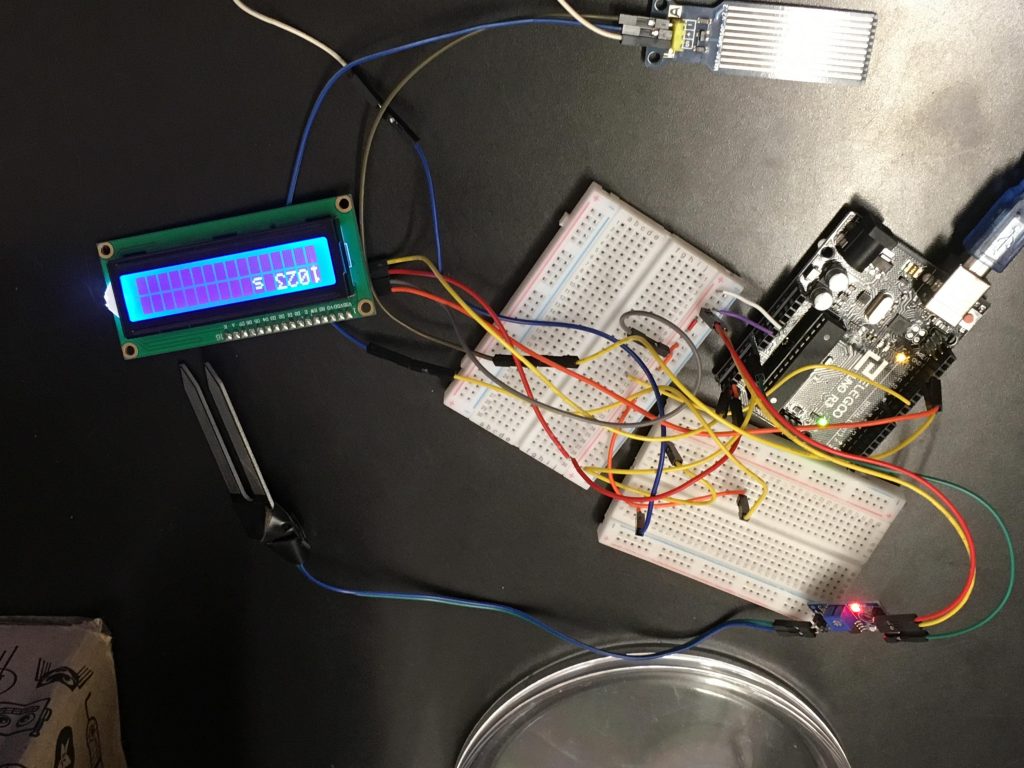
For Milestone #2, I wired and coded my LCD so the value of the sensors would be shown there rather than being shown on the Serial Monitor. This makes it far easier to check the values of the sensors.
LCD stands for Liquid Crystal Display. An LCD relies on a back-light or a reflector to send light to the LCD. The liquid crystals reflect light in different ways to write different characters. It took a fairly long time to learn how to code my LCD because i had a particular variety which is not compatible with the default library. I am glad I had to learn an entirely new library because this type of LCD is easier to wire and learning this library will save me time in the long run
#include <LiquidCrystal_I2C.h> //this is the library for the 4 pin LCD
LiquidCrystal_I2C lcd(0x27,2,1,0,4,5,6,7,3,POSITIVE);//this makes the LCD a variable called lcd. The numbers …
// …are related to the LCD’s inner wiring and specific to my one particular model.
void setup() {
lcd.begin(16,2); //This is where I specify that my LCD has two rows with 16 characters each.
pinMode(A0,INPUT);//This pin is responsible for sensing soil moisture
pinMode(A1,INPUT);//This pin is responsible for sensing water level
}
void loop() {
lcd.home(); //This tells the LCD to start printing at the beginning of the first row.
String soil=String(analogRead(A0)); // This saves the voltage from the soil sensor into a string
soil+= ” s “; // This adds the letter ‘s’ to string ‘soil’
lcd.print(soil);// this prints the string called soil on the LCD
String water = String(analogRead(A1));//This saves the voltage from the water sensor into a string.
int waterCheck = int(analogRead(A1)); //Does the same as above, except the value is saved as an int.
water += ” W “;// This adds the letter ‘w’ at the end of string water
lcd.setCursor(0,1);// This tells the computer to start printing at the beginning of the second row
lcd.print(water);//this prints the string called water
while (waterCheck<=250){//250 is an estimate, it may not be correct. Think of it as while waterCheck is low
lcd.clear();//clears everything printed on the LCD and moves the cursor to home position
lcd.print(“Add more water”);
}
lcd.clear(); //I reccomend that you add a delay at the end of the loop because without it, the LCD can…
// …change numbers so quickly that it can be difficult to read.
}
First Milestone

For Milestone #1, I wired and coded my soil moisture sensor and my water sensor. The code also adds an ‘s’ at the end to symbolize the the soil moisture sensor, or a ‘w’ to represent the water level sensor. This was done so I could tell which numbers relate to which sensor.
A sensor just alters something in the real world like current or voltage based on the presence of whatever it’s supposed to sense in the real world. For example, my soil moisture sensor has the voltage inversely related to moisture. However, my water sensor creates a higher voltage when in contact with water. In both of these sensors, the change in voltage can be interpreted to moisture levels. The program I wrote transmits 5 volts of electricity through each sensor and then detects the the number of volts that exit the sensor. However, rather than the computer stating the voltage, the computer states it in the form of a proportion, with 0 being 0 volts and 1023 being 5 volts. This process is done with an ADC pin. ADC stands for Analog to Digital Conversion. This information took me a little while to learn, because BlueStamp is the first STEM camp I have attended where I learned anything independently. This was an important change because I retain information more easily when I have to do research myself.
void loop(){
String soil=String(analogRead(A0)); // This saves the voltage from the soil sensor into a string
soil+=” s “; // This adds the letter ‘s’ to string ‘soil’
Serial.println(soil); // this prints the string ‘soil’
// The following two lines of code are identical to the previous two, just with the water sensor
String water = String(analogRead(A5));
water += ” W “;
Serial.println(water);
Starter Project
My Starter Project is the Simon Says, a game where you have to press the buttons that the computer tells you press. After you press the buttons that have lit up, the sequence of buttons gets longer. You lose if you press the wrong button. I enjoyed this project because I learned how to solder.
How it works
Next to the battery, there are resistors and transistors, allowing the current to go through the chip. Resistors restrict the flow of electric charge and ensure that not too much is supplied to the LEDs. Transistors are used divert or amplify electric current. LED stands for light emitting diodes. LEDs direct the current in one direction and also emit light. The chip connects to the LEDs, the buttons, the buzzer, the switches, and then back to the battery. The chip causes the LEDs to emit light in addition to giving and remembering the random sequences. It also activates the switches and identifies whether or not the user’s sequence is correct.
