My name is Jon. I go to Croton-Harmon high school. My starter project was an electronic die, which is exactly what it sounds like. I chose to make it because I wanted to learn how an electronic die works. For a main project I made a 4*4*4 inch LED cube, which is a metal cube with 64 LED’s attached to it. Now I never did anything representing engineering before beside LEGO Mindstorm so I had no idea what such things as soldering and an arduino is so I just threw my faith into my instructor Matt to choose a project for me to build.
Final Project: 4*4*4 inch cube – A metal cube with 64 LED’s attached to it
Here’s the instructables I used to build the cube
http://www.instructables.com/id/The-4x4x4-LED-cube-Arduino/
This is a code you can use to program the order of the lighting of the LED’s
http://www.instructables.com/files/orig/FV0/WMVC/GQYG6HKH/FV0WMVCGQYG6HKH.txt
Here’s the material you will need to build the project and plenty of solder
https://docs.google.com/spreadsheet/ccc?key=0AkS-X32YFlhbdDlNVzQxTURjam9xZUo2SGlETUpoV1E&usp=sharing
Finally here’s the schematic to the cube
http://www.flickr.com/photos/knaka/4072693764/
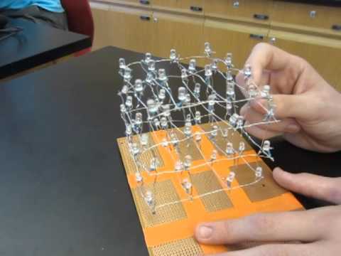
Final Project 2nd Milestone: The LED cube wiring
So technically you don’t have to do the wiring of the cube the way I did it but this is how wiring went for me. So I suggest sticking the vertical pieces of the cube through a breadboard, solder a wire to the bottom of each vertical piece of metal and attach it to an arduino board. Now for attaching wires to the arduino at first I was confused on how to put the wires in the board. Even though I had to plug in 20 wire’s into 14 I/O pins I learned it was possible to use the 6 analog pins as I/O pins. That and it doesn’t matter which wire goes into which I/O pin because as long as there’s no problem with the LED’s or the actual cube structure it should light up. But for me the directions I were using was pretty awful and didn’t mention the four vertical pieces of metal that needed to be attached to each layer of the cube so just make note of that if you follow the directions I used.
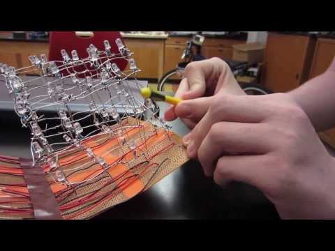
Final Project 1st Milestone: The LED Cube Structure
So for this first milestone I finished building the structure of the LED cube. Now this cube is made out of metal wire with LED’s attached to it. 64 LED’s to be exact. But not only is there 64 LED’s attached to the cube but there is a resistor attached to the bottom of each LED. So as someone could imagine there is a lot of soldering involved in this. Now the reason that a resistor needs to be attached to a leg of every LED is to help synchronize all the LED’s. That and the four metal layers are all attached to one vertical piece of metal to get a positive charge to each layer. The other leg of the LED is attached to a vertical piece of metal to get a negative charge
Reflection
When looking back on this project I will never forget the hours of soldering that went into this project. It was nothing but just soldering for hours and hours on end. Now let me just say this was just for my project and no else’s, it’s just for the the LED cube. For those who don’t know what soldering is its putting pieces of metal on other pieces of metal and then melting pieces of metal onto the stacked pieces of metal so the stacked pieces of metal stick together. So for anyone whoever wants to make this cube my suggestion is bring a pair of headphones to work because if your mind isn’t focused on anything besides melting pieces of metal you will go mad. That and no matter how stimulating that sounds you also have to spend time on rubbing LED’s on pieces of sandpaper. But for all my complaining I’m glad I built this project because seeing it light up without a hitch was pretty fantastic.
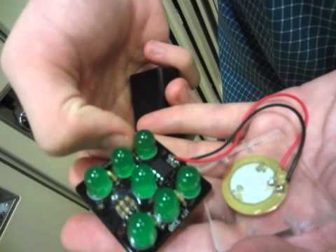
Starter Project: Electronic Dice Kit
The starter project I chose to make was an electronic dice kit. Now the way this dice works is that a pressure sensor makes a connection with the power supply so when the pressure sensor is triggered a volt of energy is released. The energy then moves through the diode that regulates the charge to the PIC chip. Based on the least significant decimal of the voltage, it sends a signal to certain resistors to turn on the LED they’re connected too. Now for my construction process…. my god was it depressing. Things just didn’t go smoothly during the construction. The first major problem I had was that in the middle of construction one of my pieces a zener diode broke and I couldn’t continue construction for an entire day which was pretty annoying. But after I got a replacement diode things still didn’t go very well because after I finished construction all the LED lights would flash sporadically which led to two entire days of painful/frustrating work unattaching and moving pieces just trying to get the LED’s stop flashing at random. Finally Dave my instructor helped me which I’m incredibly thankful for and was able to pinpoint the problem with the die which was the pressure pad under the dice was not making a solid connection with the board. So the things I took away from this project was always make sure you’re making good connections with solder, and never get so frustrated with soldering that you when your soldering you don’t notice how close the iron is to your finger because god that hurts.