IoT Weather Display
The IoT Weather Display is a customizable weather forecast device that flashes different colors, each representing a specific weather condition in any location (latitude and longitude) in the world.
Engineer
Jimmy W
Area of Interest
Computer Science / Esports
School
Galileo High School
Grade
Incoming Senior
Final Milestone
About my Final Milestone
About The Final Milestone
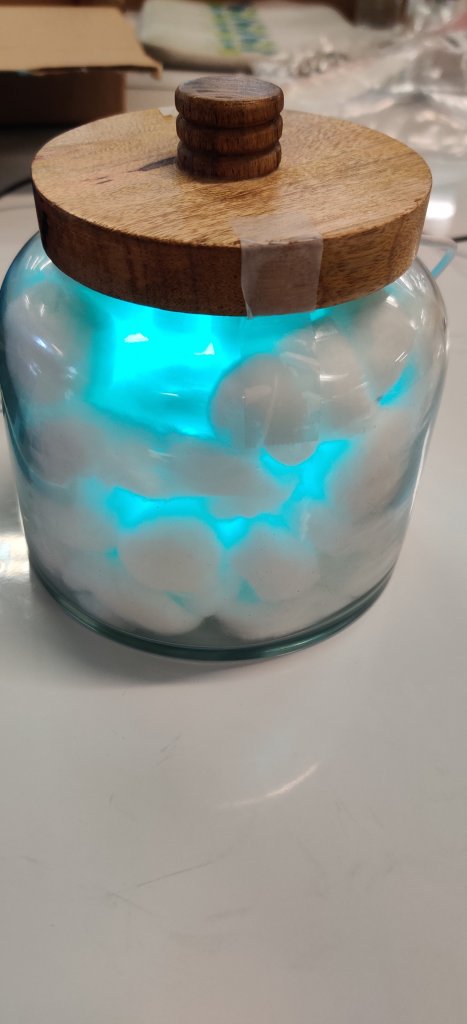
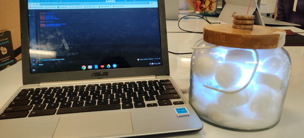
My final milestone is to light up the neopixel ring in different colors based on the weather conditions at any place in the world. The weather service that works well with Particle Photon is called Darksky, and I set up an API (Application programming interface) with the Particle website. Darksky can communicate with the particle photon by sending weather data when I input a latitude and longitude location. When weather data from Darksky is sent to the Particle, my program flashes the neopixel ring in any color based on the weather condition. For example, when Darksky reads “clear-day,” it will flash the color cyan.
First Milestone
About The First MileStone
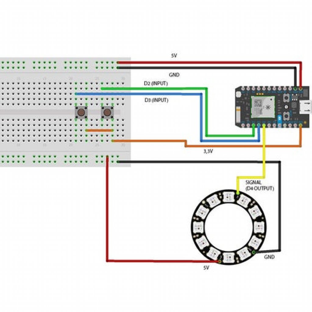
How It Works
I set up the particle photon online, then connected the particle photon, buttons, and neopixel ring electronically by wiring it according to the schematic, which created a circuit on the breadboard. After finishing the wiring, I programmed the Particle’s WEB IDE to flash different colors on the neopixel ring when pushing the button on the breadboard. After running the program code on the WEB IDE, the neopixel ring flashed Blue, White, Peach, and Yellow (each represent different weather conditions) after pressing the button.


Starter Project
About This Project
Steps
First step: Solder in the resistors, capacitors, inductor, boost converter, USB (universal serial bus), and the battery holder in the correct place on the circuit.
Second step: Plug in 2AA batteries to the battery holder, and use a voltmeter to check if the circuit generates around 5V (if it is less than 5V, then it would not charge.
Third step: Get a empty gum tin, and cut out a piece of tin to fit in the USB, then use double sided tape to tape the circuit and the batter holder inside the tin.
Last step: Test out the Minty Boost by charging a device (Ipod, smartphone).
How It Works
The Minty Boost has 2 AA batteries that generate a total of 3 volts, which flows to the inductor, then the capacitor, passes into the resistors, and finally into the boost converter. The purpose of an inductor is to store energy in a magnetic field, which will increase the voltage from 3 volts to 5. This is then passed to the capacitor, which stores energy in the form of an electric field and acts as a filter for the flow of energy. The resistors limit the flow of electrical current in an electronic circuit. This circuit is called a boost converter and is capable of boosting the voltage up to 5 volts.


