Jeremy S.
My name is Jeremy, and I am a rising senior at The Masters School. For my main project, I chose the Gesture Controlled Robot With Robotic Arm. I chose this project because I have had a little experience with robotics in the past and I wanted to try it in a more intensive and individual setting to see if it’s something I’m really passionate about. The robot and the arm attached to it are controlled by a glove that you wear on your hand. The different motions that control the robot, such as bending a finger or making a fist, can be customized as well as their functions. I chose the voice changer for my starter project, which uses a microphone and a speaker to alter your voice as you speak into it to change the pitch, make it robotic, or make it vibrato.
I think that Bluestamp was a great experience for me as an engineer. Not only did I gain the skills of coding, CAD design, and circuitry, but I also learned how to work independently and problem solve. It was a great feeling when my project finally worked, and it made me want to continue building and designing in the future. Figuring out why it wasn’t working took a lot of patience and persistence that I didn’t know I was capable of. I am very excited to continue pursuing engineering in college and beyond.
Engineer
Jeremy S
Area of Interest
Electrical Engineering
School
The Masters School
Grade
Incoming Senior
Final Project
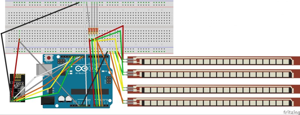
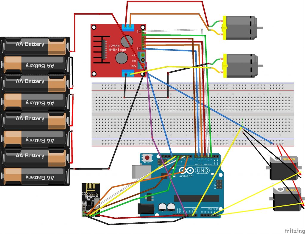
My intensive project is the gesture controlled robot. I started by making the glove. I sowed the four flex sensors onto the fingers of the glove and attached them to an arduino. I also attached an nrf chip to the arduino, which makes a wireless connection with another nrf on the robot. For the robot, I designed the chassie using CAD and 3D printed it. I then attached the two motors with wheels on them to either side and two smaller wheels to the back. Next, I put together the arm with the three servos in it with the claw at the top snd glued it to the chassie. Finally, I created two codes, one for the glove and one for the robot, that utilize the nrf’s to communicate the values of the flex sensors and turn them into commands for the robot.
For my final milestone I used nrf’s to make the flex sensors on my glove able to control the motors on my chassis. I originally planned to use Xbee’s instead of the nrf’s, but they were not working properly so I decided to switch. There is one nrf connected to each arduino, and they use radio to communicate with each other. The nrf on the glove, or the transmitter, reads the flex sensor values and sends it to the nrf on the robot, or the receiver. The receiver then gives commands to the different parts of the robot based on the values. Getting the correct code for the nrf’s took many tries because it was hard to see exactly what was causing them to not receive the correct values. I also had to rewire my entire chassis because the xbee shield broke and I could not upload code. I ended up putting a new arduino on my robot and replacing the motors with more powerful ones for better movement. There are four commands that I can do with my glove; making a fist makes the robot move forwards and bending just my thumb makes it move backwards, bending my thumb and my forefinger rotates the claw, and bending my thumb, middle, and ring fingers opens and closes the claw.
Glove Circuit Diagram

Robot Circuit Diagram


