Wave and Magnetic Field Powered Generator
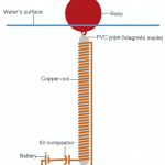
My project is a generator which gets it’s power by using ocean waves to move a magnet up and down through a copper coil repeatedly to collect electricity.
Name:
Jacob Spiegel
Areas or interest:
Aeronautical and Biomedical Engineering
School:
French American International School
Grade:
8th grader
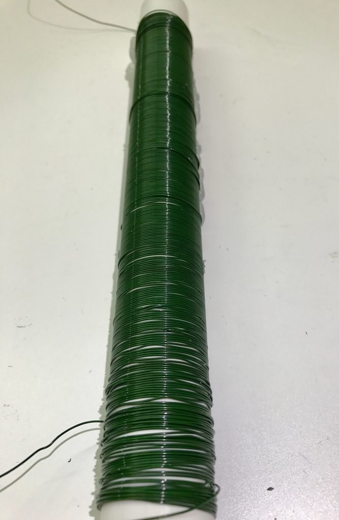
First Milestone
Inductor Coil
Second Milestone
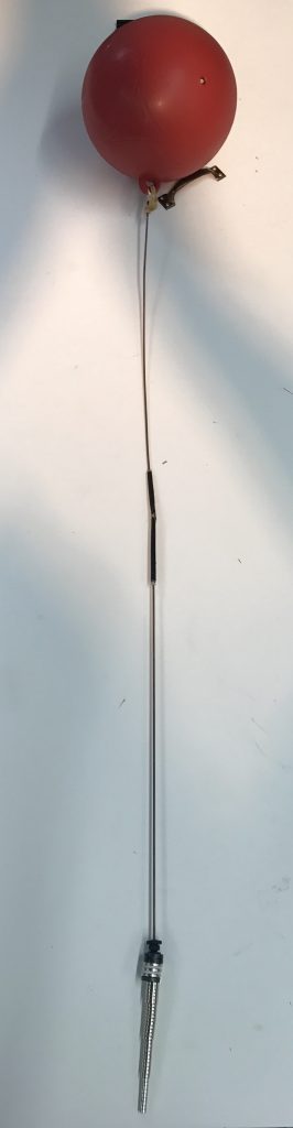
Final Milestone
My final milestone was connecting the two parts via a string at the bottom of the PVC pipe so, while it’s in the water, they don’t drift apart (this modification was added after the videos were created) and testing the project. By testing it I have concluded that, on average, my creation generates between 0.05-0.1 volts per up or down movement. During the last few days of BlueStamp I have thought of many other forms of clean energy which are based off of the same inductor-baced idea and I hope to come back next year so I may delve back in to my research in clean energy.
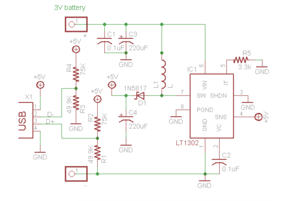
MintyBoost
Minty Boost Diagram