
Hi, my name is Jacob O. and I am going to be a junior at Los Altos High School. For my main project, I made a voice controlled robot based off of this instructable, and for my starter project I made an LED scanner.
Final Presentation

Reflection Paragraph
My time in BlueStamp has taught me a lot of what I’m truly interested in, and what I used to think I was interested because it was similar to something else. Computer science has always been the core of my interest, and BlueStamp proved just that. Thrown in an environment where there are no predefined concepts you are given and a lack of project guidelines pushes you to solve problems that are often solved for you in a school scenario (ie. do these products work together, will this product ever break). I’ve learned that due to my lack of patience, designing and physically building things often frustrates me. However, sitting behind a computer, writing code, debugging code, and modifying code, gives me a sense of accomplishment that building hardware doesn’t. Even debugging code feels much less frustrating than trying to fix wiring or attaching parts to the acrylic. In the future, I would like to pursue computer science rather than any hardware based engineering.

Instructions
1) Buy all the pieces necessary to create a voice controlled robot.
2) Attach the Easy VR Shield onto the Arduino by soldering the connector pins onto the Easy VR shield and attaching the shield to the Arduino Uno.
3) Connect a servo to the Arduino pins (one to ground, one to 5V, and one to a digital or analog pin of your choice.
4) Download a servo running software online and make sure your servo and Arduino work.
5) Download the Easy VR example software and modify it to run a servo when a keyword is recognized (code included in second milestone).
6) Attach 2nd servo using a breadboard to connect the Arduino power to both servo powers, and attach the signal wires to separate Arduino digital/analog pins. Run the program again.
7) Assemble the robot using hot glue or another adhesive to secure the Arduino, servos, and breadboard to a base (in my case acrylic).
8) Change the power supply to an external power supply, so your Arduino no longer has to run from your computer. Attach the power supply to the robot using velcro or another adhesive.
9) Download the program listed below or write your own allowing the robot to move in the direction and distance you want it to move.
10) Wire LEDS accordingly using the Arduino ground and a digital pin to make sure that your voice recognition works. Attach a third caster wheel onto the front of the robot to make the movement smoother.
Final Milestone
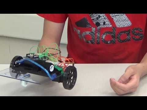

The last part of my project was largely a software challenge. I quickly realized that the example code that Easy VR gave users was not going to be sufficient to do voice recognition for 10+ different commands while having to worry about certain patterns. Furthermore, the code that the Commander gave users was heavily bugged and could not even recognize the default trigger word “robot.” Therefore, I created my own code based off the two given code examples. I utilized the Arduino main function which was an infinite loop to make it wait for a user word which the robot could work. Then, I created another function which contained a massive switch case statement that would find the group and index of the word that the user said and execute a command based on the word. These commands would often change servo speeds and delay times, so I created an if statement that would make the robot run a certain distance based on the speed and time it was given. I also added a third wheel to help the robot move more fluidly and quietly as well as changing the connection from Arduino to servo from breadboard to PCB. Lastly, to help with user interaction. I added three LEDS attached from Arduino to a breadboard to tell the user what commands the robot would recognize at a specific instance. Because I was using four groups in my voice recognition, each group had a LED assigned to it besides the trigger word. I used LEDs because they’re simple to program and effective in telling whether a command had been understood since my robot had no other way of responding to the user.
Second Milestone


The next part of my project is to make the actual chassis of the robot. To do this, I first made the robot in a 3d modeling software called Sketchup, and then I created the pieces I needed to cut in a CAD program. Then, using the acrylic we had on hand, I cut out a 6” x 9” piece, marked with permanent marker where each piece was going to go, and started hot gluing the material onto it. At first, I used a 12 volt AA powered battery pack to power the Arduino and servos, but then upon realizing its inefficiency, I switched to a rechargeable lithium ion battery. Furthermore, because the robot had two wheels, I attached another servo onto the Arduino and connected the two power supplies together using a breadboard, enabling me to use only one power source and one ground to power both servos. Lastly, I modified the Arduino sketch I created for the first milestone to move 2 continuous rotation servos on command.
First Milestone

To start off the project, I made sure my Arduino Uno worked. To do this, I first needed to download the Arduino IDE. This is the interface that Arduino Uno uses to allow users to write code and upload it into the Arduino Uno. Next, I found source code for a program that rotated a servo. I uploaded the code into the Arduino and made sure that it works. After that, I had to assemble the EasyVR shield 3.0. Unlike its predecessor, the EasyVR 3.0 doesn’t come pre-assembled. I first soldered all the pins from the EasyVR module to the shield. Then, I soldered the pins that connect the shield to the Arduino, and finally attached the Easy VR to the Arduino. Next, I want to make sure my Easy VR works, so I downloaded the Easy VR library and using their Easy VR test program, I tested if my easy VR shield worked. Next, I downloaded the Easy Vr Commander and trained some voice commands. Because I wanted to do something simple, so I programmed the command “Test” into the Easy VR and uploaded it into the shield. Finally, I modified the Easy VR Test program to include the Arduino Sweep program. Because the Easy VR test program listens to a specific command and then prints something if the command was said, I changed the print command into one that would spin the servo. This code makes the servo spin whenever I put a keyword in the robot, in this case “robot.”

My name is Jacob O. I’m a rising junior at Los Altos high School. For my introductory project, I built a LED light scanner. As you can see, when you turn the device on, the lights turn on in an ordered pattern. The first six lights first turn on, followed by the next three. Toggling the button on the right allows you to change the frequency of the lights from slow, medium, and high. The device works by the following steps. First, when the battery is turned on, the current is turned on and travels into the microcontroller where is delegates the current and splits it into 9 parts, one part for each light bulb. Then, based on the setting that it is currently is, the currents for the light bulbs that are supposed to be turned on move through the resistor which decreases the current and travels into the light bulb, turning it on. The rest of the current is stored in the capacitor. And as a result, you get a basic light show. The hardest part of this project is probably the amount of mistakes I made when I soldered the pieces together. Solder often dripped into the wrong hole, and I would spend a lot of my time trying to remove the solder with a wick.