
About Me
Hi, my name is Jacky and I’m a rising senior at Lowell High School. I chose to build an Arcade Machine that can emulate multiple arcade games by simply plugging it into a monitor. I chose this project because I have always been interested in playing video games, so I thought it would be cool to build an arcade machine that can play some of the games I played when I was small. Before coming to BlueStamp, I took Principles of Computer Science in school, in which I learned how to use Arduinos and App Programming with Lua, and I also took AP Computer Science, which focused on coding with Java. I heard about Bluestamp from guest speakers in our AP Computer Science class and became interested in this program, because I wanted to build something and learn more about engineering.
Overall, I learned a lot of new things at Bluestamp, such as electrical work, wiring, soldering, and 3d modeling. My project wasn’t as difficult as I thought it would be at first, and although I encountered some issues along the way, it went pretty smoothly. I’m glad I was able to learn more about engineering, because the only experience I had coming into Bluestamp was coding.


In this project, I build an Arcade Emulator Cabinet using a few pieces of wood, buttons, a ton of wires, joysticks, and a Raspberry Pi. I first built the cabinet by using 4 pieces of wood. I measured and drilled holes for the buttons and joysticks. After that, I wired everything in to an IPAC, which has multiple terminals for different inputs and sends signals to the Raspberry Pi depending on which buttons are pressed. The IPAC is a board with terminals for different buttons and sends signals to the Raspberry Pi depending on which button is pressed. I felt like the wiring was the most difficult part of the project because I have over a hundred wires in my cabinet and it gets confusing. After I finished the wiring, I plugged the cabinet into the TV, but the controls were all messed up and I had to rewrite the config file for the inputs. Finally, once I got the Arcade Machine to be fully functional, I added in LEDs in the buttons to make them light up as a modification.

Raspberry Pi
IPAC 2 Interface
Arcade Joystick
Push Buttons
Wires
12 Volt Power
8 GB SD Card
Wood
Wood Screws
Solder Wire
Power Adapter
Bill of Materials
Manual: Part 1
Manual: Part 2
Retropie Image
Controls Configuration
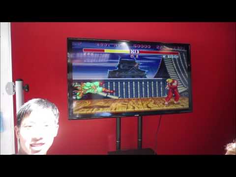
My third milestone is finishing all the wiring and getting the arcade cabinet to be fully functional for both single player and multiplayer. I wired in the 2nd player’s joystick and the rest of the buttons similar to how I wired it for the first player. I also extended the green GND chain to include the 2nd player’s joystick and the new buttons. Afterwards, I plugged the arcade cabinet into the TV and launched Street Fighter II, but the controls were all messed up, and some of the buttons were corresponding to the ESC and P key on the keyboard, which would exit out of the game every time it was pressed. I did some research afterwards and rewrote the .cfg (config) file for MAME, the arcade emulator, and plugged in the USB keyboard to the Raspberry Pi to correctly configure the controls. In Street Fighter, the top row is Light, Medium and Heavy Punch, and the bottom row is Light, Medium, and Heavy Kick. After completing this milestone, we were able to play Street Fighter 100% the way it was intended to be played in an arcade. We were also able to play other arcade games such as 1943: The Battle of Midway and Mortal Kombat without any issues.
Green wire = GND
Blue wire = Player 2 Joystick input
Yellow wire = Player 2 Buttons input


My second milestone is wiring in a joystick and some buttons to make a basic one player arcade system working. The joystick has 8 terminals total, 2 for each direction. One of them is used for the input, while the other one is used to hook up to GND. I used solder to wire in the inputs to the IPAC, which sends instructions to the Raspberry Pi depending on which direction the joystick is moved in. The buttons also have a terminal for input and GND. I wired the buttons’ input the same way as the joystick, in the IPAC. Afterwards, made a wire chain that that went through each button and each direction on the joystick and connected the loose end to GND. GND, or ground is the reference point in an electrical circuit from which voltages are measured. I then installed the retropie image into the Raspberry Pi, a software that emulates games and installed a few games. I was able to launch a few games, but the only one that was playable was Super Mario Bros because it runs NES which has pre-configured controls, and can be played using only 3 inputs (A, B, START), unlike the other classic arcade machine games. One difficulty I had with this milestone was wiring the joystick. It was hard to tell which direction each terminal was, and upon starting up the Raspberry Pi, I realized that the inputs were wrong, and I had to rewire it. I also had a bit of trouble installing games to the Raspberry Pi and had to rewrite the image, but I learned a lot about wiring in this milestone.
Green wire = GND
Red wire = Joystick input
White wire = buttons input
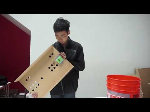
My first milestone is creating the cabinet for the Arcade machine using a few pieces of wood, wood screws, and a drill. I cut out a large 58 cm x 36 cm wood board to use to mount the joysticks and buttons to. I then cut out another 2 pieces of wood 58 cm x 10 cm to support the main board so that I have plenty of space under the main board for the wiring, the Raspberry Pi, and the IPAC. I used a large flat head screw to drill 13mm radius holes for the joysticks and buttons, based on a design I made with Sketchup. The most difficult part was drilling wood screws through the solid wood, as I constantly had to remove the wood scraps while drilling. However, I learned a lot about using power tools and designing 3d models in this milestone.

For my starter project, I built the Gram Piano using Sparkfun’s kit. It is a mini piano that can play different notes by tapping on it, and can play three different octaves as well. It includes sharps and flats, and plays from C to C. It can also play a pre-installed melody by the single press of a button. This project allowed me to learn how to solder and familiarize myself with some fundamental components of electrical work (e.g. resistors, capacitors, transistors).
- Batteries: Provide power for the board
- Capacitors: Store energy in the form of an electrostatic field from battery
- Resistors: Limit current to prevent the board from burning up
- LED: used to display whether piano is on or off
- Switch: Wired to the battery and LED, used to turn the piano on/off.
- Microprocessor: Sends commands to tell the board what to do.
- Speaker: Plays the sounds.
- Potentiometer: Twists, allows you to play in three different octaves.
- Button: Plays a pre-installed melody.