My name is Jack, and I’m a rising senior at the Head-Royce School . I found the BlueStamp Engineering program through one of my teachers at school, and I thought this would be a good opportunity to expand both my programming experience as well as introduce myself to more hands-on work. I’ve been taking computer science classes at school since my sophomore year and developed a strong passion for coding as a result. I wanted to see how I can apply what I already know about coding to other fields of operation, and engineering seemed like an interesting junction between programming and hardware. The reason I chose a GPS navigation system as my main project was because I thought understanding the basics of how a navigation system organizes its data and operates under the hood was a good way to learn how hardware and software can be synthesized into something useful. Overall, I enjoyed my 4 weeks at BlueStamp. Although my final device was not as developed as I had hoped, I’m glad I persevered through all the challenges that came up. It was undoubtedly frustrating when I would get stuck on an issue I was expected to solve on my own, but being able to present a functioning prototype in the end also comes with an undeniable sense of pride.
Project Overview
Summary Video
Elaboration
In the video, I went over the general process of my project and briefly explained the biggest hurdles that I have to overcome to reach each of my milestones. For a more detailed explanation of each milestone, you can find their descriptions and videos below. As for my final project phase itself, I’ve gotten my GPS navigation system to track and display where I am, even as I am moving, around roughly a 5 block radius circling the BlueStamp classroom. In terms of future modifications and improvements, I would like to expand the navigation system’s range to cover a bigger section of the Bay Area as well as design a case for my project so that the device looks more homogenous and can be handled more easily.
Final Modifications
Since my second milestone, I finished debugging a lot of the issues that were showing up with the location dot on the screen. First, there was the problem with refreshing the dot so that when you change location, you only get a single dot on the map instead of a continuous line starting from your starting location. To solve this, I edited my code so that it would re-upload the map image back onto the screen with a 500 millisecond delay to make it smoother. Next, as I was walking around the block to test the GPS, I noticed that the location dot was going in the exact opposite direction, both longitudinally and latitudinally. To fix this, I simply switched the positions of the boundary values in the map calculation functions. Finally, I noticed that the scale of the boundaries themselves don’t match with the map itself. For example, when I walked to the end of a block, my GPS would show that I still needed to walk a little more to reach the corner. This prompted me to adjust the distance between the two longitudinal boundaries and the two latitudinal boundaries, respectively. Through a day or two of trying out different values, I finally found the right proportions for my map boundaries to produce a decently accurate tracking of my location.
Documentation
Milestone 2
My second milestone is uploading a map file up to my display screen and printing out a dot onto the map based on the coordinates from my GPS module. However, right now the dot doesn’t actually point to our location on the map because the boundary data I assigned to the map file was pretty arbitrary (I just eyeballed the edges on Google Maps and got values from that).
After milestone 1, I started working on the coding part of my navigation system. I looked at the code from the link on the project book, but I found out that the author’s project doesn’t use the same parts that I have, so his code runs a lot differently. Another issue with using his code was that he’s from the Netherlands, and all the boundary data he prepared was only usable within his country. I decided to try looking for a different GPS project online for help, and I found one on elecfreaks.com. This project mainly used parts that I have, and the instructions seemed pretty simple. The best part about this new set of instructions was that its method of getting map files wasn’t specific to any region, so I can use it to cover the Bay Area. Unfortunately, the program used to get these map files couldn’t work for me, and I even tried running on 3 different computers before giving up on it. After this, I decided that I would have to write my own code from scratch as well as find my map files to use.
To get my own map files, I started looking around for some GeoTIFF files online since I thought those maps would already be georeferenced, making it easier for me to get some boundary points to use later. I found a GeoTIFF map file of San Francisco and used an image processor called Irfanview to split the map into smaller BMP files so that it would be easier for me to upload onto my LCD display. Unfortunately, I wasn’t sure how to extract each file’s coordinate information, especially now that everything was in BMP format. Instead, I decided to just try to manually assign boundary coordinates to each map file in my code. I uploaded the map file that covers the Mission District onto my SD card and then used Arduino’s map function to calculate where to print out a point on the screen to correspond to our supposed location given from the GPS module. The map showed up on the screen and a red dot appeared, but the location displayed was about a block off. I realized that this was probably due to how arbitrary my assigned boundary lines were, so my next milestone would be to refine my numbers down to be more accurate. However, this milestone still helped confirm that the mechanics for my navigation system code works.
Milestone 1
My first milestone is getting both the GPS module as well as my display screen to respond correctly. I’ve successfully installed the wiring for both objects to my Arduino Uno board, meaning that I’m more or less finished with working on my actual parts.
For the display screen, I checked it using an example from an Adafruit graphics library I downloaded and tweaked a bit. There were two wiring options to test, but I needed option 2 specifically to work because it was mode that would allow me to use the SD card to upload images (i.e. my map for the GPS system). For some reason, only option 1 was working even though I checked that the wiring was correct and my code was perfectly fine for option 2. I contacted the author of the tutorial I was reading about what was happening, and while I was waiting for him to respond, I starting working with my GPS module. I found a code sample online that would let me test if my GPS module was properly sending back its data (longitude, latitude, and time stamp) to the Arduino, but when I ran it, I got a “No GPS Detected” print on my serial monitor. I looked at the Troubleshooting section online for the program to try and fix this, but I was still having the same problem even after trying all of its suggested solutions. I e-mailed the seller of the GPS module (sparkfun.com) for help, and after a few days of meticulously inspecting every single detail of my set-up with him, he suggested that I run it again using an Uno board (I was on a Mega board the whole time). He told me that the Mega board can’t do software serial over some pins, which might be preventing the GPS’ data from being sent correctly. I switched my board and when I ran the GPS test again, and all the right data showed up on my serial terminal.
Schematic Source
I suspected that the board might’ve also been the reason why my display wasn’t working, so I tried running the graphics test again on the Uno board. At this point, the display tutorial author was completely lost as to why my display wasn’t working so I was trying to figure out how to fix it on my own. However, once I ran the graphics test with the Uno board, the display lit up and worked perfectly. With option 2 working, I also tested to see if I could now access images from the SD card using another example sketch that came with the Adafruit graphics library. I had to change a bit of the code, especially the pin assignments, but once I uploaded the sketch, my image showed up on the display.
For my next milestone, I have to get a georeferenced map file for my GPS to use and incorporate that into the program for the actual navigation system.
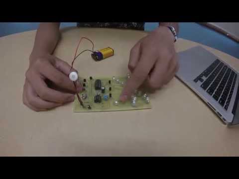
Starter Project
For my starter project, I made the Exploding Light Sound Organ. This project allowed me to learn how to solder as well as familiarize myself with some fundamental components of electrical work (e.g. resistors, capacitors, transistors). How the device itself works is that it lights its LEDs in certain patterns based on the sound signals it receives from its microphone.
Parts & Their Functions
- Microphone- receives sound signals for interpretation by device (main input to initiate system)
- Electrolytic Capacitors- stores energy so it can help avoid sudden, large changes to the voltage → stabilizes power supply (shunts AC and leaves a steady DC voltage as its output)
- Resistors- limits current going into the LEDs to a safe value as to prevent them from blowing out
- Trimmer Resistors- allows the user to adjust degrees of resistance to control 1) the sensitivity of the system to sound and 2) sequencing speed for the display
- Transistors- 2 functions → 1) first 3 transistors are used to amplify the sound signals received by the mic to a level strong enough to drive the sequencing display circuitry of the ICs. 2) other 4 transistors are used as switches to direct the voltage to light up the LEDs according to how the ICs dictate the display
- IC1 & IC2- parts of control for device → IC1 responds to the sound signals it receives by sending out clock pulses on pin 3. These pulses are sent to IC2, and every time IC2’s pin 14 receives a pulse, it shifts its output to a different pin. These output pulses are sent to the last 4 transistors that light up the LEDs in the pattern it receives the pulses from IC2.
- LEDs- primary display for gadget
- Battery Snap- attach 9V battery for source of electrical power