
Object Detection with Raspberry Pi
My project is a Raspberry Pi powered Object Detection program. It uses a trained Tensorflow model and YOLO algorithm to detect and classify objects in images and live videos.
Engineer
Gerard S
Area of Interest
Computer/Mechanical Engineering
School
Regis High School
Grade
Incoming Junior
Reflection
My BlueStamp Engineering experience was overall quite educational, fulfilling, and enjoyable. Throughout the whole 3 weeks and 3 major milestones, I learned a series of skills, ranging from soldering, wiring, Arduino fundamentals, the basics of the Raspberry Pi, and strengthening of my Python coding. All of these proved very useful in the creation of my Object Detection program, and allowed me to create a working product that could read and classify objects in still images and live video. I think that my experience here has not only helped me practice my hobby (coding), but also greatly broadened my horizons to other types of engineering and its real-world applications. I believe that in the near future I will pursue an internship and most likely a career in my passion, computer/mechanical engineering.
Thank you to all the instructors, directors, and my parents for giving me this opportunity.
Final Milestone
For my Third Milestone, I made my object detection software able to 1) Read any still images and 2) Give confidence scores in the terminal for the different possible guesses.
I achieved still image object detection in 3 steps
-
Install the Image Classifier
-
Test Default Image
-
Test image of your choosing
1. Install Image Classifier
I began by creating a directory for my Tensorflow models and then cloning them in from Github:
mkdir tensorflow
cd tensorflow
git clone https://github.com/tensorflow/models.git
2. Test Default Image
Then I changed directories into the imagenet folder and ran the python script that was in the folder:
cd models/tutorials/image/imagenet
python3 classify_image.py
If done correctly, the output should display an 89% of the image being a panda (the default image) (outlined in green in Figure 7).

3. Test Image of your choosing
To choose my own image to detect, I began by creating a new directory in home/pi where the images would be stored. After I chose the name “mypics” for the folder, I navigated into home/pi/models/tutorials/image/imagenet and opened classify_image.py. In that python file, I scrolled down until I found ‘cropped_panda.jpg’ (use the search tool with Ctrl F) and changed it to ‘home/pi/mypics/image.jpeg’. I then saved the file and exited. Now anytime I wanted to detect an image, I would save it as “image.jpeg” in the mypics folder and run the same code in the terminal as before:
cd models/tutorials/image/imagenet
python3 classify_image.py
I tried an image of a komodo dragon and got the results shown in figure 8.

What I Learned | Mistakes
My final milestone did not give me many problems, and it was not too difficult since there were only 3 major steps. The only issue I ran into was with choosing my own image. Every time I ran the python script, I got an error message saying that my chosen image could not be found or does not exist. After some trial and error, I realized that I just had forgotten to put quotation marks on my file name in the python code in step 3. This milestone did not teach me anything brand new but it helped reinforce my coding skills, especially in Python.
Second Milestone
For my Second Milestone, I ran my object detection software using a pre-trained model. When completed, the Pi Camera was able to 1) put a live video feed on my screen, 2) draw bounding boxes around any objects it detects and 3) label them. It additionally gives “confidence scores” for each object, which are percentage values that indicate how certain that the program is correctly identifying the object.
To reach this point, I took many tips and suggestions from Edje Electronics’s Github tutorial: https://github.com/EdjeElectronics/TensorFlow-Object-Detection-on-the-Raspberry-Pi
The Tensorflow Object Detection API can be outlined in 5 steps:
-
Update the Raspberry Pi
-
Install Tensorflow
-
Install OpenCV
-
Install and Compile Protobuf
-
Set up TensorFlow directory structure and the PYTHONPATH variable
1. Update Raspberry Pi
To update the Raspberry Pi, I opened the terminal and issued
sudo apt-get update
sudo apt-get dist-upgrade
Be warned that these updates may take a while depending on how it has been since your Pi has last been updated. In my case, these took a few hours.
2. Install Tensorflow
To install Tensorflow, I began by creating a folder called “tf” in the home directory using the following code:
mkdir tf
cd tf
Then I downloaded Tensorflow from a Github repository using this code:
wget https://github.com/lhelontra/tensorflow-on-arm/releases/download/v1.8.0/tensorflow-1.8.0-cp35-none-linux_armv7l.whl
Next I installed Tensorflow and the accompanying LibAtlas package by issuing this:
sudo pip3 install tensorflow
sudo apt-get install libatlas-base-dev
LibAtlas provides many important algebraic processes that are necessary for the calculations that my program has to make.
The rest of the dependencies needed can be found on the Github tutorial listed earlier.
3. Install OpenCV
After installing some more dependencies, I installed OpenCV using:
pip3 install opencv-python
4. Compile and Install Protobuf
Next, I needed to install the image processing package, Protobuf. I installed and compiled protobuf by issuing the following code in this order into the terminal:
sudo apt-get install autoconf automake libtool curl
wget //add link below to this
https://github.com/google/protobuf/releases/download/v3.5.1/protobuf-all-3.5.1.tar.gz
tar -zxvf protobuf-all-3.5.1.tar.gz
cd protobuf-3.5.1
./configure
make
make check
sudo make install
cd python
export LD_LIBRARY_PATH=../src/.libs
python3 setup.py build –cpp_implementation
python3 setup.py test –cpp_implementation
sudo python3 setup.py install –cpp_implementation
export PROTOCOL_BUFFERS_PYTHON_IMPLEMENTATION=cpp
export PROTOCOL_BUFFERS_PYTHON_IMPLEMENTATION_VERSION=3
sudo ldconfig
Once these were completed, I rebooted my Pi using sudo reboot now
5. Set up TensorFlow Directory Structure and PYTHONPATH Variable
To make the Tensorflow directory and be able to change directories (cd) into it, I issued mkdir tensorflow1 and cd tensorflow1. I then downloaded the tensorflow repository from Github by typing
git clone –recurse-submodules https://github.com/tensorflow/models.git
To modify the PYTHONPATH environment variable, I opened the .bashrc file and added the following code to the last line of the file:
export PYTHONPATH=$PYTHONPATH:/home/pi/tensorflow1/models/research:/home/pi/tensorflow1/models/research/slim
I finished this process by navigating back into the home directory and adding this code:
cd /home/pi/tensorflow1/models/research
protoc object_detection/protos/*.proto –python_out=.
cd /home/pi/tensorflow1/models/research/object_detection
Finally, I downloaded the pretrained object detection model and unpacked it by issuing:
wget http://download.tensorflow.org/models/object_detection/ssdlite_mobilenet_v2_coco_2018_05_09.tar.gz
tar -xzvf ssdlite_mobilenet_v2_coco_2018_05_09.tar.gz
Detect Objects
To detect objects, I downloaded the object detection Python script from: https://raw.githubusercontent.com/EdjeElectronics/TensorFlow-Object-Detection-on-the-Raspberry-Pi/master/Object_detection_picamera.py
After connecting my Pi Camera to the Raspberry Pi, I ran this script by issuing the following code and waiting for the video frame to appear on the monitor
python3 Object_detection_picamera.py
What I Learned | Mistakes
I ran into quite a few issues throughout this process. One of them occurred when I was trying to install tensorflow, for I kept running into an error message reading “these packages do not match the hashes from the requirements file.” I overcame this by modifying the download code. Another problem resulted from the fact that my Pi was running on Python’s 2.7 version and not 3.5, which prevented me from installing .whl files containing “cp35.” Once I had all of my code ready and plugged in my Pi Camera, I got many error messages saying “no data received from sensor.” I solved this by trying out other people’s cameras and concluding that mine was simply faulty. The debugging challenges that I had to face in this milestone were not very straightforward, but they have taught me great Googling and research skills for my next milestone and for the future in general.
First Milestone
My first milestone was to get the Raspberry Pi software running on my monitor.
The Raspberry Pi setup is a 5 step process
-
Format the SD card
-
Download NOOBS onto your computer
-
Extract NOOBS zip file into formatted SD card
-
Eject SD card and insert it into Raspberry Pi along with the necessary peripherals
-
Boot up and configure the Raspberry Pi software
The necessary materials for this process are the following:
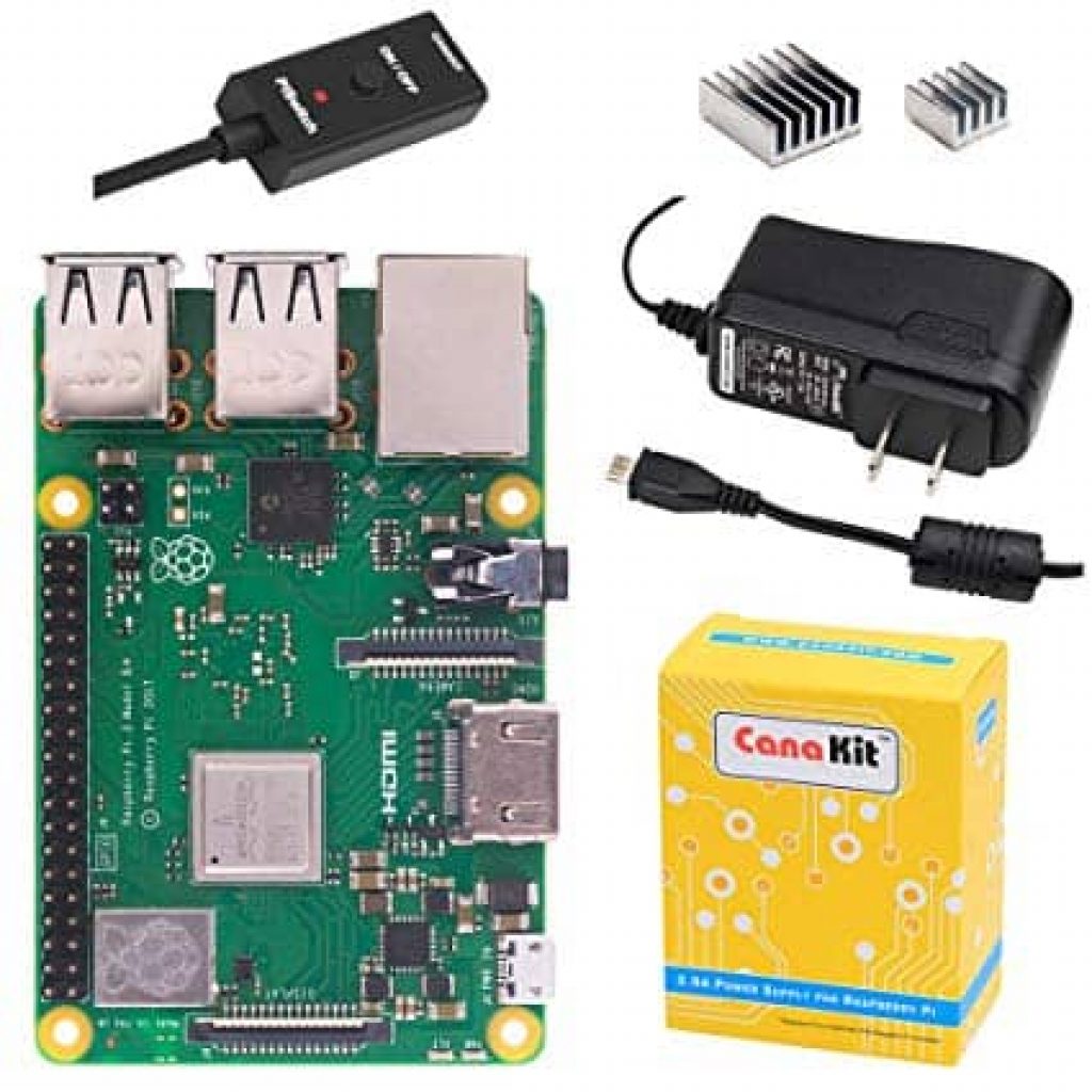
- Raspberry Pi 3 B+
- Raspberry Pi power supply
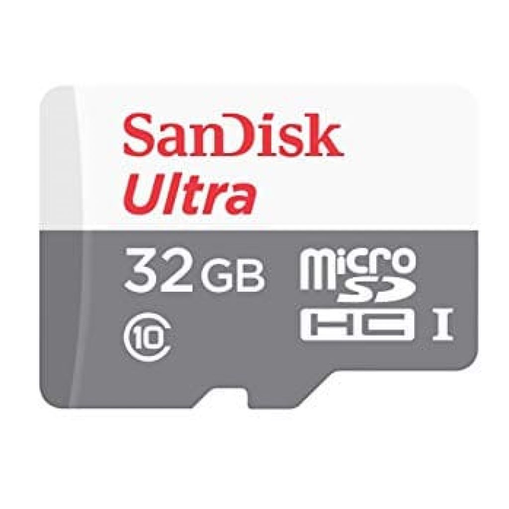
- Micro SD card (32Gb recommended but larger still works)
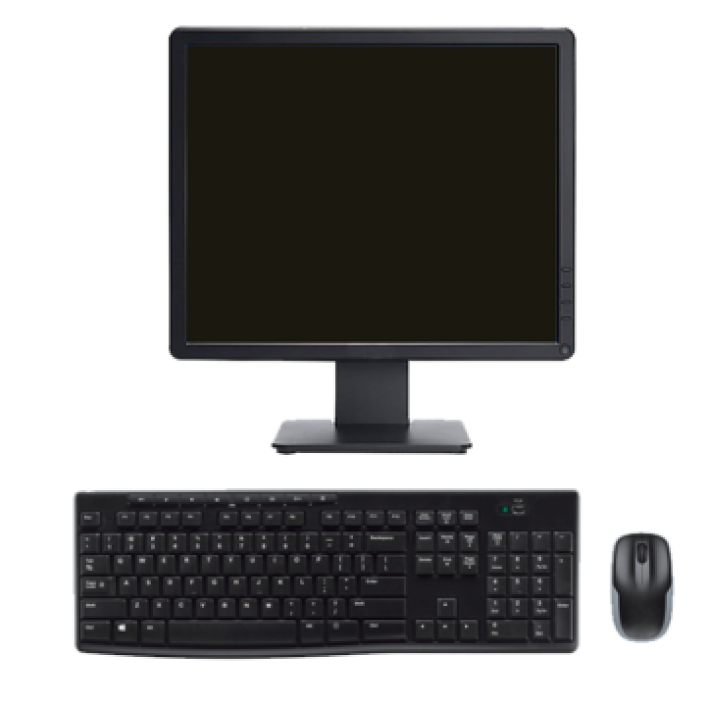
- USB Mouse
- USB Keyboard
- Monitor (with a power supply)
- HDMI cable
- A running computer with at least 3Gb of free space (for NOOBS download file)
1. Formatting the SD card
For 32 gigabyte SD cards:
I downloaded the SD card formatting application from this link: https://www.sdcard.org/downloads/formatter/. Then I scrolled down and selected my operating system (mine happened to be Windows)(Figure 2). Once I accepted the terms and conditions, the application was sent to my downloads folder as a zip file. After opening the zip file, the program launched. From there I clicked Run>Next>Next>Install>Finish. Then I ran the program and selected the drive letter that pertained to my SD card (make sure to double/triple check this so that you don’t erase important files from your computer). Then I clicked “format”. (Figure 3)


For any SD card larger than 32 gigabytes (Mine was 128Gb so I had to do this):
First I used the previous formatting software for 32Gb SD cards.
Since Raspberry Pi’s will only boot on SD cards in “FAT32” format, which comes by default on only 32Gb cards, I had to download the following software to convert my 128Gb card’s “exFAT” to “FAT32”: http://www.ridgecrop.demon.co.uk/index.htm?guiformat.htm. Once I launched the software, I was prompted by a new screen to select my drive and click “start” (Figure 4).

2. Downloading NOOBS
I went to the official NOOBS download page (https://www.raspberrypi.org/downloads/noobs/) and selected the version labeled “Offline and network install” (Figure5).

3. Extracting NOOBS into formatted SD card
I went into my downloads folder and right clicked on the NOOBS zip file and selected “Extract All.” I also chose the SD card as the target folder for these extracted files.
4. Eject the SD card and connect the necessary peripherals to the Raspberry Pi
- First I properly ejected my SD card and then I plugged it into the slot on the underside of the Raspberry Pi.
- Then I plugged my mouse and keyboard into the Pi’s USB slots
- Next I plugged the monitor into its power supply and connected it to the Pi via HDMI cable.
- Finally I connected the Pi to its power supply
*These steps are illustrated in Figure 6.

5. Booting up the Raspberry Pi and configuring it
- After plugging in the peripherals into all the appropriate ports, the Pi’s built-in LED started blinking green and the boot up screen came up on the monitor. (Be warned that the initial necessary downloads may take some time)
- Once the Pi was booted, I selected my desired operating system and language (Raspbian and English respectively).
- Finally I went through the configuration setup by selecting a Wifi network, selecting a time zone, etc.
What I learned/Mistakes
Everything went well throughout this whole process minus the booting step. Every time I plugged in my power supply to my Raspberry Pi, I was met by error messages on my monitor. After troubleshooting for hours and replacing monitors, HDMI cables, and even Raspberry Pi’s, I narrowed down the issue to the formatting of the 128Gb SD card. It was in “exFAT” format instead of “FAT32”, which is the only format that the Raspberry Pi can read. This issue was solved by the second software downloaded in step 1. I learned from this experience a very useful way of troubleshooting, which is narrowing down variables to eventually isolate the problem.
Starter Project
My starter project is an Arduino proximity sensing device. It uses an HC-SR04 ultrasonic sensor as an input and a Piezo Buzzer as an output. As a user/object nears the ultrasonic sensor, the buzzer activates, with the pitch being raised at 4 distance intervals.
Completed Starter Project
How it works
All of the distances are calculated by the ultrasonic sensor’s emission of ultrasonic waves (Figure 1). It uses the speed of sound and the time it takes for the waves to bounce back from an object to measure distance (distance = speed*time). When the sensor detects something 20 centimeters away it makes a buzzing noise at 400 hertz, at 15 centimeters 600 hertz, 10 centimeters 800 hertz, and 5 centimeters 1000 hertz.

The Code
// defines pins numbers
const int trigPin = 9;
const int echoPin = 10;
const int buzzerPin = 11;
// defines variables
long duration;
int distance;
void setup() {
pinMode(trigPin, OUTPUT); // Sets the trigPin as an Output
pinMode(echoPin, INPUT); // Sets the echoPin as an Input
pinMode(buzzerPin, OUTPUT); // Sets buzzerPin as an Output
Serial.begin(9600); // Starts the serial communication
}
void loop() {
// Clears the trigPin
digitalWrite(trigPin, LOW);
digitalWrite(buzzerPin, LOW);
delayMicroseconds(2);
// Sets the trigPin on HIGH state for 10 micro seconds
digitalWrite(trigPin, HIGH);
delayMicroseconds(10);
digitalWrite(trigPin, LOW);
// Reads the echoPin, returns the sound wave travel time in microseconds
duration = pulseIn(echoPin, HIGH);
// Calculating the distance
distance= duration*0.034/2;
// Prints the distance on the Serial Monitor
Serial.print("Distance: ");
Serial.println(distance);
if (distance < 5){
  tone(buzzerPin, 1000, 500);
  digitalWrite(buzzerPin, HIGH);
} else if (distance < 10){
  tone(buzzerPin, 800, 500);
  digitalWrite(buzzerPin, HIGH);
} else if (distance < 15){
  tone(buzzerPin, 600, 500);
  digitalWrite(buzzerPin, HIGH);
} else if (distance < 20){
  tone(buzzerPin, 400, 500);
  digitalWrite(buzzerPin, HIGH);
}
}
What I Learned | Mistakes
I did not run into many problems in my hardware and software. After getting a “USB Power Surge” error message, I had to restart my laptop and Arduino IDE several times to be able to upload code to the board again. Other than that and a few wiring mistakes that i had to correct, everything ran smoothly. Although only a simple and small project, this served as a very important foundation for my main project, since I was able to learn soldering, the basics of the arduino interface, wiring, and some more code syntax.