
Hi! My name is Eric, and I am a rising junior at Mills High School. My starter project is the Big Time Watch, and my main project is a RC Hovercraft. I got the inspiration to make a hovercraft from previous Bluestamp students as well as Instructable pages (links below). I’ve had experience in engineering from my school’s robotics team, where I now manage the construction department, and from an engineering class in school. Prior to Bluestamp, I mostly worked on the hardware aspect of many projects, with limited experience with electronics and programming. I am glad that I got the opportunity to join Bluestamp because it has reinforced my interest in engineering and it has exposed me to electronic engineering and programming, giving me more options to think about when thinking about what major to pursue in college.
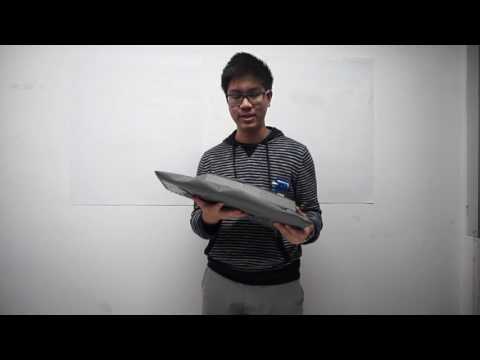
Final Product


Resources:
http://www.instructables.com/id/Very-Fast-RC-Hovercraft/
http://www.instructables.com/id/Radio-Controlled-Hovercraft/
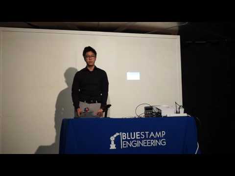
Presentation and Reflection
Reflection: Bluestamp has been a great experience for me. It has not only inspired me to continue to make projects on my own, but it has fortified my interest in becoming an engineer. The feeling of having a product that I made with my own hands is amazing, especially because its a vehicle. I have always loved vehicles, especially cars. This time, I wanted to make something different than robots with wheels, and I’m glad I did. The journey up until the finished project was not without obstacles. The biggest obstacle I had was the issue with communication between the ESCs and the controller. This was solved by connecting them with the Arduino. I have learned to always persevere, because in the end, the reward of having a successful product is a great feeling.
Milestone #3
My third milestone was mounting all the electronics and putting it into the body of the hovercraft. After getting all the electronics to work, I assembled the top layer of the hovercraft and attached it on top of the base. The function of this layer is to cover all the electronics and keep them in place. After that was finished, I mounted all the electronics into hovercraft. I used a piece of depron to both seal the area around the lift fan and protect the wires from getting into the way of the fan. In order to mount the thrust fan onto the servo, I used a piece of wood. I hot glued the wood to the servo horn and put a screw through the wood and the fan. After everything was mounted, it was finally time to test the hovercraft. The bag inflated very quickly, but the bag had one area near the middle that would inflate more than the other parts of the bag. This resulted in the hovercraft not hovering and having contact with the ground which increases the friction. This meant that the thrust fan was unable to propel the hovercraft forward. After research online and instructors’ advice, we settled on a shape for the skirt where the middle of the skirt would be secured to the base of the hovercraft. I sewed the skirt through the four layers of the base. After this was done, the holes had to be redesigned because my initial holes started to redirect air outwards. What was needed was a high-pressure cushion of air below the hovercraft to generate lift below the hovercraft, allowing the hovercraft to glide over surfaces. Now, there are two rectangular holes near the center of the skirt allowing air to escape, and they allow the hovercraft to hover. During all of this, I learned how the design skirt is the most pivotal part of making the hovercraft hover.

Milestone #2
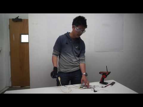
My second milestone was putting together the electronics for the hovercraft. There are five components; the battery, a switch, the ESCs, the receiver, and the fans. The battery is a 7.4V lithium polymer battery. The battery is directly connected to a switch, which is useful because it is able to cut off power quicker than unplugging the battery. It also proved very useful when I was testing the fan because there were many issues in that process. When the switch is turned on, it supplies power to the two 30A BEC ESCs. The ESCs are the most vital part of this circuit. ESC stands for Electronic Speed Controller. It connects directly to the receiver to interpret the information sent by the controller. It also sends power to the receiver. The ESC can receive signals between 700 and 2000 microseconds. The ESC interprets this and then converts the DC power input into a three-phase AC output and send it to the brushless motors. This activates the motors. Brushless motors are unique in the way they work. There are magnets on the rotor with electromagnets surrounding it. The electromagnets exert a magnetic force to rotate the rotor and the fan. There were two main issues in this process, with the one that occurred later being very time-consuming. The first issue was that the ESCs that were first ordered were the wrong kind. They were OPTO ESCs, which lack a power wire going to the receiver along side the signal wire and the ground wire. This was an issue because as a result, the receiver would not turn on. This was solved by buying BEC ESCs, which limits the voltage provided by the 7.4V battery to 5V for the receiver. However, another issue arose after connecting the ESCs to the fans and the receiver. When the controller’s trigger is at neutral the fan was running. However, when the trigger is pulled back it turns off. Using the wheel on the side of the controller yielded the same results. However, the servo functioned as it should have with all the controls. We then scoped out the signal sent out by the receiver to the ESC and from the ESC using an oscilloscope. Below are the conclusions I made after using the oscilloscope.
Oscilloscope Notes:
1.When measuring the signal coming out of the receiver, the signal appears to be correct, with differentiations between neutral, full throttle, and minimum throttle. Neutral’s period appeared to be the middle ground between the two.
2.When measuring the signal coming out of the ESC, the signal is flat when the trigger and wheel are pulled back and are sending a signal at neutral and minimum throttle
3.When the endpoints are adjusted below 90%, they do not change the signal. Adjusting the endpoints between 90%-99% does not seem to differ from 100%.
4. The old ESCs output the same signal as the new ones.
At this point, there was a strong indication that the issue was with the ESCs, but I could not be 100% sure that they were at fault. I tried changing some settings in the controller, but it did not change anything to help the issue. I went back to the idea that there was something wrong with the ESC’s. After much research online, I concluded that it was an ESC calibration issue. Even though I followed the calibration sequence perfectly, the controls still were incorrect. As a result, I resorted to calibrating the ESC through an Arduino Uno. After uploading the code to the ESC and testing it, another issue arose. Upon startup, the motor would stutter, rotating back and forth. Later, I tested the ESC that I did not reprogram, and the same stuttering occurred. I then tried one of the OPTO ESCs and connected it to the receiver alongside one of the BEC ESCs. While the same throttle issue that happened before was still present, it no longer stuttered on startup. In the end, to calibrate the ESC and the controller so that the controls are in the right orientation, I used an Arduino Uno. The Arduino is connected to the receiver and receives the signal sent by the controller. The Arduino then emits a signal to the ESC so that the fans can turn on. As a result of this issue, I have learned many things. I have learned how to troubleshoot using the oscilloscope and how to use an Arduino.
Wiring Diagram

Thrust ESC: Signal connects to Pin 4 on Arduino. Ground connects to Arduino.
Lift ESC: Connects to Channel 3 on receiver.
Servo: Connects to Channel 1 on receiver.
Arduino: Connects to Channel 2 on signal and ground on receiver. Connects to VCC on 5V.
Code
// width w/ trigger held: 1.2 millisecond 7.5% duty cycle// period: 16 msfloat period = 16;
float triggerHeld = 1.2;
float triggerReleased = 2;
float myMin = 976;
float myMax = 2000;int readPin = 6;
int outPin = 4;float timeOn() {
while (digitalRead(readPin)) { // wait to go low again}while (!digitalRead(readPin)) { // wait to go high again}double start = micros();
while (digitalRead(readPin)) { // wait to go low again}return (micros() – start); // return time it took to go from high to low
}
void writeToESCS(float width) {
int myLength = map(width, 976, 2000, 1490, 990);
for (int i = 0; i < myLength / 24; i++) {
digitalWrite(outPin, HIGH);
delayMicroseconds(24);}
digitalWrite(outPin, LOW);
}
void setup() {
pinMode(readPin, INPUT);
pinMode(outPin, OUTPUT);
Serial.begin(9600);
Serial.println(“hello world”);
}void loop() {writeToESCS(timeOn());
}
Milestone #1

My first milestone was building the base and the making the skirt. The base is made out of depron, which is a foam typically used for RC planes. The base is four layers of depron stacked on top of each other. The first layer allows the electronics and the top layer to rest on it. The second layer is there to hold the fan that provides lift in place. The third and fourth layers are the most important parts. The fourth layer is there so that once the air hits it, the air is deflected and travels outward. The third layer is comprised of several pieces that are designed to redirect the air throughout all sides of the hovercraft, to send the air into the skirt. The skirt is made out of PVC-coated polyester. In the future, the skirt will have holes at the bottom to provide lift for the hovercraft. There is a foam piece to reinforce the skirt.
I designed the base and the top layer using Sketchup. This was a great learning experience for me because I had no prior experience with Sketchup. In the beginning, it was a little difficult because I had no idea how to abnormally shaped objects, which the hovercraft obviously is. By the end, with a lot of trial and error, I was easily able to make the pieces I wanted in a relatively short amount of time. In this process, I learned an immense amount of information on how to use Sketchup. I now feel confident in creating 3D models using the software.


Top Layer Base 1st Layer Base 3rd and 4th Layer
The biggest challenge I had during this process was sewing together the skirt. The material was very thick and it was difficult to sew together all the folds. This was not aided by the fact that I had very little experience with sewing. Sewing did not seem to result in a very airtight skirt, so I ultimately resorted to super gluing the folds together and it bonded very well. It was also immensely faster than sewing. I used RC glue to seal the skirt, in order to minimize air leaking out. Another challenge I had was designing the top layer, which I have not assembled onto the base yet. One of the panels in my design on Sketchup would not fill in. This was ultimately solved by deleting the problematic half, mirroring the good half, and subsequently attaching it.
I used this resource as a reference for the design of the layers and this as a rough reference for the overall look of the hovercraft.
Starter Project

The Big Time Watch works very much like the digital clocks people use at home. The battery provides current to the micro controller. The capacitor connected to the micro controller is there so that in case of a voltage drop, the capacitor can step in and maintain the voltage so that the micro controller does not restart. The micro controller makes the crystal (usually a flat piece of quartz) oscillate 32768 times per second by applying a voltage. The micro controller then counts the oscillations and generates electric pulses one time per second. This information is then relayed to the display. The display only turns on when the switch is closed, and it send a signal to the micro controller to turn on the display. The biggest challenge I faced was getting the threaded insert into the acrylic. This was ultimately solved by compacting the tip and then inserting them. I learned how digital clocks keep track of time by using quartz.
Watch Schematic

wiow