Sip-and-Puff Controller
Welcome! My name is Elizabeth and I am currently a rising senior at Notre Dame High School. My extensive project, the sip and puff controller, aims to grant those with a disability that impairs their hands the ability to successfully type the letters of the alphabet.
Elizabeth T.
Area of Interest:
Electrical Engineering and Human Factors Engineering and Computer Science
Reflection
When imagining what BlueStamp would be like, I found myself picturing a room full of individuals with stoic expressions concerned solely on the completion of the task at hand. Despite my prior expectations, I was met with a group of individuals where when it was time to work there was no shortage of furrowed brows, yet all were exceedingly passionate about the environment in which they were in. The sense of balance that I was greeted with among the students truly set the stage for my time here. There was a sense of fear of not knowing enough, but over time every question served as an element that only furthered my development. Every speed bump was a chance for me to become an even stronger individual and prove to myself that the goal I set at the beginning was achievable. I was inspired to persevere through the challenges due to the lingering hope of creating something that would target a marginalized and often forgotten population. My desire to achieve this goal was not hindered by the completion of my final milestone, which instead sparked a want to further expand my device’s capabilities. The last six weeks have truly been a blessing that I will be forever grateful for.
My Final Milestone
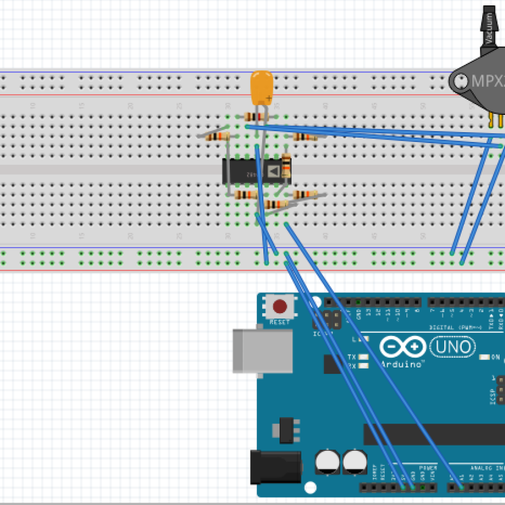
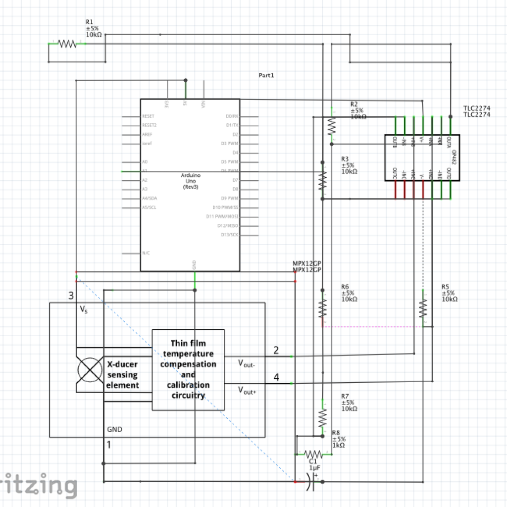
The Hardware
Check out my code on GitHub
My Second Milestone
My First Milestone
Starter Project

