
My name is Eduardo and I am 18 years old. I attend Cardinal Hayes High School in the South Bronx. I want to be an aerospace engineer because, since I was a kid, I loved watching movies related to flying and exploring outer space. I think that being an aerospace engineer will give me the opportunity to maybe become an astronaut and explore the heavens. I would even like to meet life beyond earth. For that reason, I chose to make an RC Hovercraft for my main project. When deciding whether or not to build a hovercraft, I thought ab0ut planes and their components. The Hovercraft was the closest thing that came to dealing with motors, propellers, and the like, therefore, I decided it would be enriching to build something that is somewhat related to airplanes.
Main Project: RC Hovercraft

Final Milestone
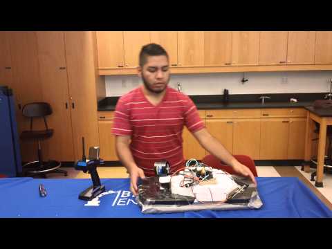
My third and final milestone was, for me, the hardest of all. This accomplishment breaks up into two parts: mechanical assembly and soldering.
Mechanical Assembly- Although assembling and building was a tedious task, I enjoyed doing so and also found the process to be quite easy compared to other things I had to do. For the mechanical assembly of my motors, I had to make sure my motors were stable enough on the bases I had made for them. I also had to make sure my fans were not chipped or damaged in any place because that would affect their efficiency. In addition, I had to place the servo I used at an angle that would allow for its neutral state to be straight and facing the back of the hovercraft without bumping into other parts of the hovercraft when rotating.
Soldering- The soldering part of my project was, I believe, one of the toughest parts of all. Soldering was particularly difficult because sometimes the soldering irons would not work properly and I would not be able to solder correctly or I would occasionally burn the rubber covering of copper wires. Soldering was also somewhat annoying because, often, I would have to de-solder wires and then solder them together again. During the de-soldering process, wires would sometimes get damaged, which would create complications when trying to re-solder. Despite the various difficulties I experienced, I managed to solder my motor wires to my ESCs, my ESCs to a on/off switch, and the switch to a power source (Lipo battery).
Here is the bill of materials I used: https://docs.google.com/spreadsheets/d/1C0cNcEx876Tn0ADzCAUx6xCutoBX2PCzjSIs4PIaaKU/edit#gid=0
Here is the build plan I followed: https://docs.google.com/document/d/1hqoITI6uElwHUcrHNfh8M49DhCjvXYJjEWeWVEoy9j8/edit?pli=1
Second Milestone
My second milestone consisted on mounting two motors, the thrust motor and the lift motor. The first motor to be mounted was the lift motor. To mount the lift motor, I cut a small piece of wood (about 5″ per side) and used it as a base for the motor. After cutting the small wood base, I screwed the motor onto the piece of wood using a cross mount. Once the lift motor was screwed onto its base, I used Epoxy glue to attach the base to the platform I made with tongue depressors. Finally, once the glue was dry, I proceeded to place the propeller on the shaft of the lift motor and applied some glue so the propeller would not unscrew itself from the motor shaft. For the thrust motor, I first mounted an MG995 Tower Pro servo onto the hovercraft. Finally, I proceeded to glue the base of the thrust motor to the top of the servo, which would allow the thrust motor to change direction and, in turn, the hovercraft would be able to change direction.
First Milestone
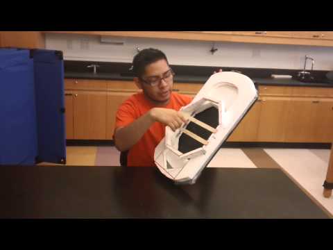
My first milestone is the completion of the mechanical assembly of my RC Hovercraft. For the hovercraft’s body, I used four pieces of Styrofoam with measurements of 1″X12″X12″. Using Epoxy as an adhesive, I glued together two foam pieces for the bottom platform of the hovercraft and two pieces for the top platform. While letting both pieces dry overnight, I proceeded to create a lift duct for my hovercraft. I created the lift duct by cutting 8 pieces of Styrofoam with dimensions of 1″X1 1/2″X 13″ and an angle at one end with a measurement of 45 degrees. After cutting the foam pieces, I glued the pieces together with Epoxy glue and let them dry overnight. Next, I created a small platform that stretched across the lift duct. To do so, I used three tongue depressors for each side of the platform and then glued them together with Epoxy glue. Once the bonds were strong enough, I, once again using Epoxy glue, pasted down both platforms parallel to one another across the lift duct. To match the shape of my lift duct, and to give space to my propeller, I then used an X-Acto knife to cut out the shape of the lift duct on both platforms of Styrofoam. While cutting, I made sure t cut at a slight angle so that air would flow into the lift duct. After this, I glued together two pieces of tarp so that I had a wide enough surface area to cover the bottom platform of my hovercraft. While doing so, I made sure to leave an overlap of two inches on all sides. Once I had finished measuring my tarp, I pasted it down to the bottom platform using duct tape. Next, I made two medium, asymmetrical holes at the ends of the tarp so that friction reduces and there is upward force. Finally, I used Epoxy glue to paste the top platform to the bottom platform and the lift duct to the top platform.
Starter Project
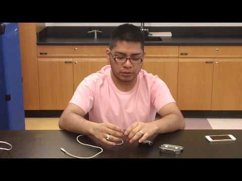
As my beginner project for BlueStamp, I chose to build a voice changer. During the first week of BlueStamp, I worked diligently on my project. I soldered wire, cut wire, de-soldered, etc. However, I made a few beginner mistakes that cost me a lot of time, effort, and materials. My main mistake was that, when trying to de-solder, I burnt the circuit board that contained all the parts I needed to solder. Because my circuit board was burnt, my voice changer would not work even though it would turn on. After discussing my starter project with Randy, he gave me a MintyBoost, which is a portable phone charger, so that I could build it. On the first day of the second week of BlueStamp, Randy gave me a quick lesson on how to solder and de-solder correctly. After doing so, Randy let me work on the new project by myself. This time, I paid close attention to the way in which I inserted materials and especially to the way I soldered- I tried to get everything right the first time so I would not have to de-solder and run the risk of ruining my project again. After completing my Portable Phone Charger, I learned what its different parts do. Here is what I learned: Two AA batteries send three volts to the MintyBoost and the Boost Converter Chip turns those three volts into five volts. The MintyBoost has many parts, including resistors. Resistors lower the input from three volts to two volts because they control the current. For the phone to be charged, the boost converter chip “boosts” the input voltage of the device to five volts. The output of the boost converter chip is greater than the input value of the device. Other materials also include capacitors, diodes, and the IC Chip (which I now know stands for Integrated Circuit). For the voltage to stay at five volts, the capacitors store electrical charges. The diode is the component that makes the current to flow in one direction towards the USB port. The IC chip helps boost the device’s voltage to five volts from the original three volts from the batteries.